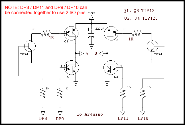
Darlington transistor H-Bridge
Safely Build Program a H-Bridge
Link to YouTube video for this webpage: Arduino Programming H-Bridge
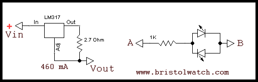
LM317 constant current source.
The two items above serve the following purposes: limit the current so wiring mistakes or bad programming won't blow your transistors or MOSFETs. The other is simple LED polarity indicator to show the polarity is switching - make sure this works BEFORE connecting a motor!
Make sure any H-bridge is connected to a microcontroller, not push button switches, etc.
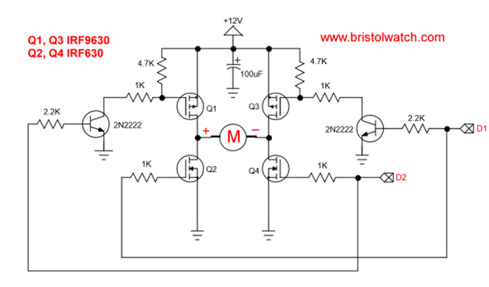
Also see H-Bridge Motor Control 2 Input Diagram.
The program below uses direct port register access to assure proper switching. Two switches are connect to and DP2 and DP3. Press either one motor will turn on. Press reset to turn motor off.
To better understand Arduino port register commands see Arduino Port Registers Revisited
/*
  Forward-Reverse H-bridge control
 DP2 - Forward
 DP3 - Reverse

 DP8 - Q1 PNP PB0
 DP9 - Q2 NPN PB1
 DP10 - Q3 PNP PB2
 DP11 - Q4 NPN PB3

 Forward Q1, Q4 ON
 Reverse Q2, Q3 ON
 */

void setup() {
  pinMode(2, INPUT);
  pinMode(3, INPUT);
  digitalWrite(2, HIGH);
  digitalWrite(3, HIGH);
  // DP 8,9,10,11,13 output
  DDRB = DDRB | 0b00101111;  // 4 bytes
  // All off
  PORTB = PORTB & 0x00; // 2 bytes
}

void loop() {

  if (!digitalRead(2))   {
    PORTB = PORTB & 0x00; // off
    delay(500);
    PORTB = PORTB | 0b00101001;
  }

  if (!digitalRead(3))   {
    PORTB = PORTB & 0x00; // off
    delay(500);
    PORTB = PORTB | 0b00000110;
  }
}
See How I got into Electronics
- Arduino Port Registers Revisited
- Digispark ATtiny85 with MCP23016 GPIO Expander
- Safely Build Program a H-Bridge
- Build H-Bridge Motor Control Without Fireworks
- MOSFET H-Bridge for Arduino 2
- PICAXE Projects
- YouTube videos:
- Simple Power Distribution for Prototype Board
- Program Arduino Ports for Speed and Control
- Digispark ATtiny85 with GPIO Expansion
- Safely Program H-Bridge Motor Controller
- Build H-Bridge Motor Control without Fireworks
- MOSFET H-Bridge for Arduino 2
- Arduino Projects Revisited Revised
- Programming ADS1115 4-Channel I2C ADC with Arduino
- Arduino uses ADS1115 with TMP37 to Measure Temperature
- Connect Arduino to I2C Liquid Crystal Display
- Arduino Reads Temperature Sensor Displays Temperature on LCD Display
- Arduino with MCP4725 12-bit Digital-to-Analog Converter Demo
- Videos
- Arduino with ADS1115 4-Channel 16-bit Analog-to-Digital Converter
- Arduino with MCP4725 12-Bit DAC
- Constant Current Circuits with the LM334
- LM317 Constant Current Source Circuits
- Introduction Hall Effect Switches, Sensors, and Circuits
- Microchip PIC related videos:
- How to Use K150 PIC Programmer
- Microchip PIC16F628A Basic H-Bridge Motor Control
- Microchip PIC16F628A Counts BCD on 8 LEDs
- PIC16F84A Operates H-Bridge Motor Control
- PIC16F84A Operates MOSFET H-Bridge
- Using Velleman K8048 PIC Development Board
- Microchip PIC16F84A H-Bridge Motor Control
- Microchip PIC16F628A Basic H-Bridge Motor Control
- PICAXE Operates H-Bridge Motor Controller
- PICAXE Micorcontroller Controls Motor Speed - Direction
- PICAXE Projects
- Arduino Port Registers Revisited
- Digispark ATtiny85 with MCP23016 GPIO Expander
- Safely Build Program a H-Bridge
- Build H-Bridge Motor Control Without Fireworks
- MOSFET H-Bridge for Arduino 2
- Web Master
- Gen. Electronics
- YouTube Channel
- Arduino Projects
- Raspberry Pi & Linux
- PIC18F2550 in C
- PIC16F628A Assembly
- PICAXE Projects
Web site Copyright Lewis Loflin, All rights reserved.
If using this material on another site, please provide a link back to my site.