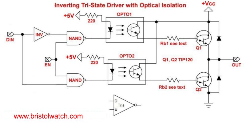
Fig. 1
Optocouplers for TTL-CMOS Logic Level Shifting
by Lewis Loflin
Here I'll illustrate using optocouplers to perform voltage logic shifting between TTL and CMOS devices. Optocouplers also isolate output transistor voltages from low-voltage digital logic.
See the following related pages:
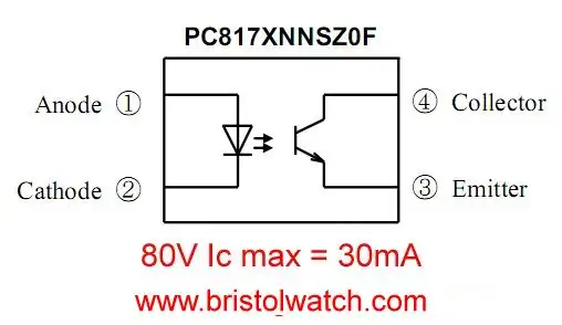
Fig. 2 PC817 Optocoupler.
An optocoupler is usually an infra-red LED emitter on the input and a photo detector on the output. Here I'm concerned with the most common type with a photo transistor.
Fig. 2 is the PC817 optocoupler. Transistor rating is 80-volts at 30mA. The collect-emitter voltage and current ratings are the main limitation of the device.
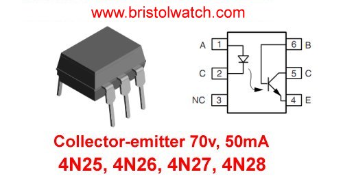
Fig. 3
Fig. 3 is pin connection for 4N25, 4N26, 4N27, 4N28 optocouplers. The output transistor rating is 70-volts at 50mA.
Functionally it is no different from PC817 other than lower collector current.
When calculating current limit the current to 75% of maximum.
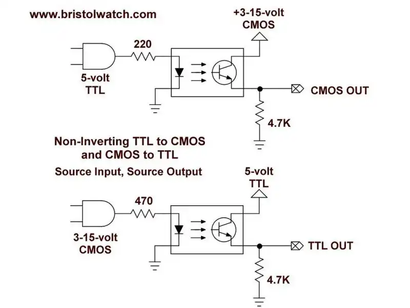
Fig. 4
Fig. 4 uses a 4N25 optocoupler to form non-inverting TTL to CMOS logic level shifter.
One should understand the concepts of source and sink.
The switching device will either sink the current, or create a path to ground. The other end of the load if connected to the often positive supply voltage or +Vcc.
In the source configuration the switching device will connect the load to +Vcc.
In Fig. 4 the input is a TTL 5-volt source connection. The output is also a source switching setup.
A HIGH or 5-volts on the input produces a HIGH 15-volts on the output. This is non-inverting - HIGH in is HIGH out. We merely shifted the voltage level.
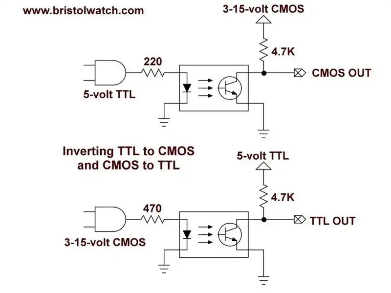
Fig. 5
Fig. 5 uses a 4N25 optocoupler to form non-inverting CMOS to TTL logic level shifter.
Here we have a source input from a 15-volt CMOS circuit to source 5-volt TTL circuit. Again this is non-inverting - HIGH in is HIGH out.
Input is source, output is source.
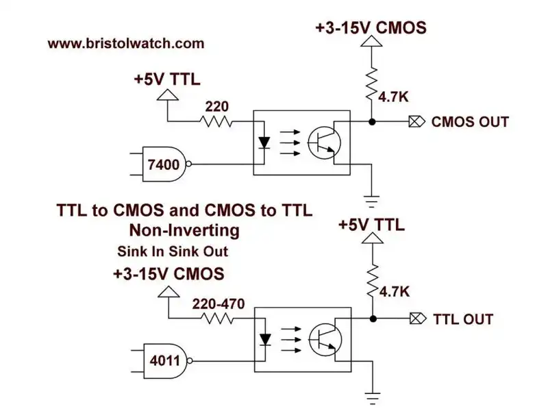
Fig. 6
Fig. 6 uses a 4N25 optocoupler to form non-inverting CMOS to TTL logic level shifter.
We have a sink CMOS input that when LOW turns on the LED. The output is 5-volt TTL goes LOW when the transistor is turned in. This is non-inverting - LOW input is a LOW output.
Input is sink, output is sink.
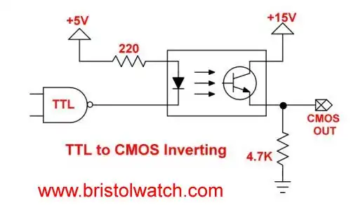
Fig. 7
Fig. 7 uses a 4N25 optocoupler to form inverting TTL to CMOS logic level shifter.
Fig 7 is identical to Fig. 6 other than output circuit we changed the resistor and photo transistor. The logic level is inverted - LOW input produces a HIGH output.
The input is sink, output is source.
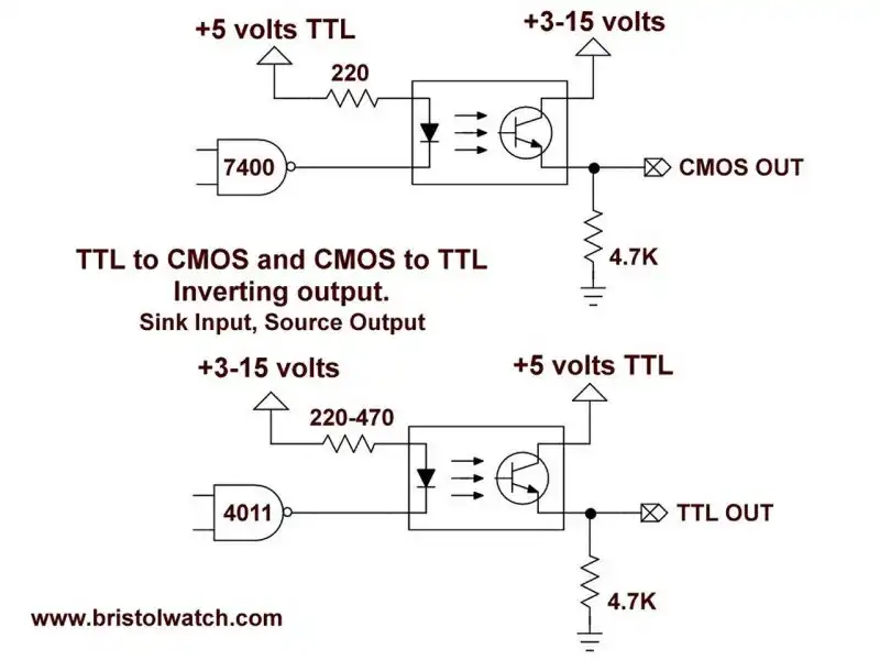
Fig. 8
Fig. 8 uses a 4N25 optocoupler to form inverting TTL to CMOS logic level shifter.
Input is source and output is sink.
- Exploring Solid State Relays and Control Circuits
- Comparing Photo Triac, Photo SCR Opto-Couplers
- Light Activated SCR Based Optocouplers Circuit Examples
- Silicon Controlled Rectifier Review and Circuits
- Silicon Controlled Rectifiers Connected as Power Triacs
- Insulated Gate Bipolar Transistor IGBT Circuits
- Current Limiter Circuits for Opto-Coupler LEDs
- VOM1271 Photovoltaic MOSFET Driver Circuits
- Current Limiter Allows Safe Testing of Zener Diodes, LEDs
- 3 Amp LM741 Op-Amp Constant Current Source
- Bidirectional Solid State Relay Circuits
- Simple Solid State Relay for Low Power LED 120V Lamps
- Build High Power MOSFET Directional Switch Relay
- Optical Isolation of H-Bridge Motor Controls
- All NPN Transistor H-Bridge Motor Control
- Basic Transistor Driver Circuits for Micro-Controllers
- ULN2003A Darlington Transistor Array with Circuit Examples
- Tutorial Using TIP120 and TIP125 Power Darlington Transistors
- Driving 2N3055-MJ2955 Power Transistors with Darlington Transistors
- Understanding Bipolar Transistor Switches
- N-Channel Power MOSFET Switching Tutorial
- P-Channel Power MOSFET Switch Tutorial
- Build a Transistor H-Bridge Motor Control
- H-Bridge Motor Control with Power MOSFETS
- More Power MOSFET H-Bridge Circuit Examples
- Build a High Power Transistor H-Bridge Motor Control
- H-Bridge Motor Control with Power MOSFETS Updated
- Opto-Isolated Transistor Drivers for Micro-Controllers
- Comparator Theory Circuits Tutorial
- Constant Current Circuits with the LM334
- LM334 CCS Circuits with Thermistors, Photocells
- LM317 Constant Current Source Circuits
- TA8050P H-Bridge Motor Control
- All NPN Transistor H-Bridge Motor Control
- Basic Triacs and SCRs
- Comparator Hysteresis and Schmitt Triggers
- Comparator Theory Circuits Tutorial
- Photodiode Circuits Operation and Uses
- Optocoupler MOSFET DC Relays Using Photovoltaic drivers
- Connecting Crydom MOSFET Solid State Relays
- Photodiode Op-Amp Circuits Tutorial
- Optocoupler Input Circuits for PLC
- H11L1, 6N137A, FED8183, TLP2662 Digital Output Optocouplers
- Optical Isolation of H-Bridge Motor Controls
- All NPN Transistor H-Bridge Motor Control
© Copyright 2019 Lewis Loflin E-Mail