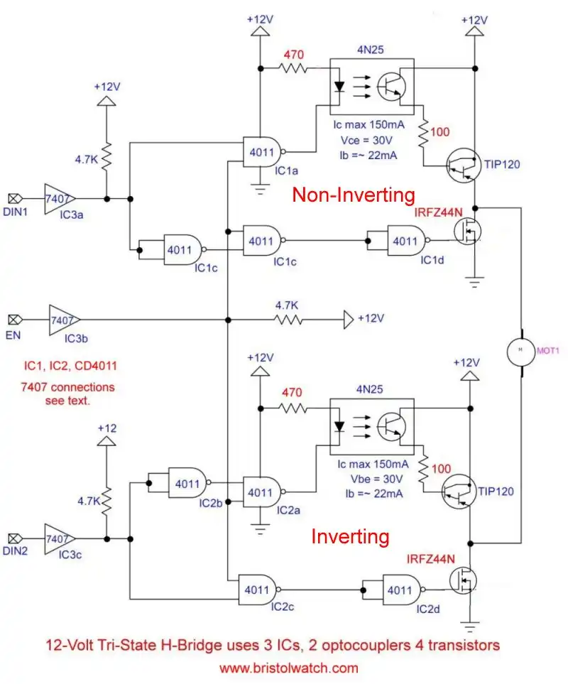
Fig. 1 Tri-state H-Bridge motor control uses optocouplers.
Tri-State H-Bridge Uses Optocouplers
by Lewis Loflin
YouTube Video Opto-Coupler Interfacing H-Bridge Circuits
By adding optocouplers to a tri-state switch we isolate 3.3 to 15 volt logic from high voltage output transistors.
An optocoupler operates at a higher voltage than a MOSFET transistor. The gate-source voltage for a MOSFET is often 20 volts.
The Optocoupler coupled with a Darlington transistor allows the use of higher voltages than a p-channel MOSFET. This is limited by the collector-emitter voltage and collector current of the optocoupler.
For information on the digital gates see Review Connecting Digital Logic and Transistors. It also has the 7407 interface circuit not shown.
The circuit example in Fig. 1 does two things. Q2 bipolar transistor was replaced with a N-channel power MOSFET.
To get above the 5-volt limit created by the 5-volt digital logic, I've used an optocoupler. This consists an LED infrared emitter and in this case a NPN photo transistor.
When the optocoupler transistor is switched on current flows though Rb1 turning on the TIP120 Darlington transistor.
+Vcc is the motor voltage limited by the collector-emitter voltage of the optocoupler. Rb1 is calculated to limit base current of Q1 and optocoupler circuit. 100 Ohms works for 12 volts.
A higher motor voltage can be used but must be kept separate from the CMOS logic voltage limited to 15 volts.

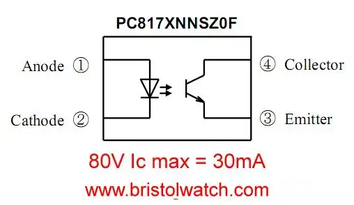
Fig. 2
Fig. 2 is the PC817 optocoupler. I bought 50 for $5 from Ebay. It has a transistor voltage limit of 80-volts and a collector current of 30mA.
The formula to calculate Rb1 is +Vcc - 2V / 25mA. I chose 25mA to stay under the 30mA limit of the optocoupler transistor. Q1 is a TIP120 NPN Darlington with a gain of 1000+.
See Tutorial Using TIP120 and TIP125 Power Darlington Transistors.
For the power MOSFET Q2 see:
N-Channel Power MOSFET Switching Tutorial.

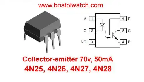
Fig. 3
Fig. 3 shows the outline of the 4N25, 4N26, 4N27, 4N28 type optocouplers. The transistor has a collector-emitter breakdown voltage of 70V and a maximum current of 50mA.
For more information on optocoupler circuits see:
- Optocoupler MOSFET DC Relays Using Photovoltaic drivers
- Connecting Crydom MOSFET Solid State Relays
- Photodiode Op-Amp Circuits Tutorial
- Optocoupler Input Circuits for PLC

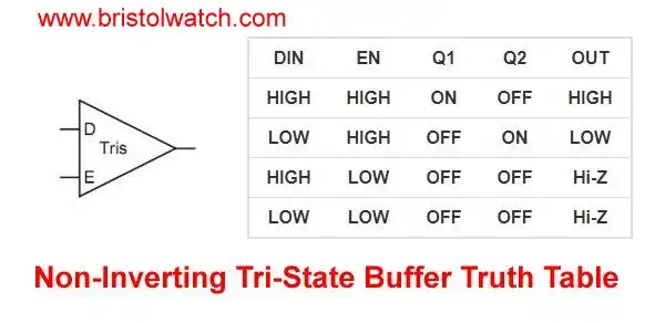
Fig. 4
Fig. 4 is the truth table for Fig. 1.
- Optical Isolation of H-Bridge Motor Controls
- All NPN Transistor H-Bridge Motor Control
- Basic Transistor Driver Circuits for Micro-Controllers
- ULN2003A Darlington Transistor Array with Circuit Examples
- Tutorial Using TIP120 and TIP125 Power Darlington Transistors
- Driving 2N3055-MJ2955 Power Transistors with Darlington Transistors
- Understanding Bipolar Transistor Switches
- N-Channel Power MOSFET Switching Tutorial
- P-Channel Power MOSFET Switch Tutorial
- Build a Transistor H-Bridge Motor Control
- H-Bridge Motor Control with Power MOSFETS
- More Power MOSFET H-Bridge Circuit Examples
- Build a High Power Transistor H-Bridge Motor Control
- H-Bridge Motor Control with Power MOSFETS Updated
- Opto-Isolated Transistor Drivers for Micro-Controllers
- Youtube videos:
- Driving High-Power Darlington Transistors
- Four MOSFET Tri-State Switch
- Overview Toshiba IGBT Application Notes
- MOSFETs and Electron Flow
- 3.3 Volt Logic Controls H-Bridge TTL Input
- H-Bridge Driving Large Motor
- Simple Digital Interface Circuits
- Optocoupler Interfacing H-Bridge Circuits
- Why Your MOSFET Transistors Get Hot
- Unrelated videos:
- Reality of Recycling Low-Value Ewaste
- Magnetron Operation and Free Magnets
- Exploring Solid State Relays and Control Circuits
- Comparing Photo Triac, Photo SCR Opto-Couplers
- Light Activated SCR Based Optocouplers Circuit Examples
- Silicon Controlled Rectifier Review and Circuits
- Silicon Controlled Rectifiers Connected as Power Triacs
- Insulated Gate Bipolar Transistor IGBT Circuits
- Current Limiter Circuits for Opto-Coupler LEDs
- VOM1271 Photovoltaic MOSFET Driver Circuits
- Current Limiter Allows Safe Testing of Zener Diodes, LEDs
- 3 Amp LM741 Op-Amp Constant Current Source
- Bidirectional Solid State Relay Circuits
- Simple Solid State Relay for Low Power LED 120V Lamps
- Build High Power MOSFET Directional Switch Relay
- Optical Isolation of H-Bridge Motor Controls
- All NPN Transistor H-Bridge Motor Control
- Basic Transistor Driver Circuits for Micro-Controllers
- ULN2003A Darlington Transistor Array with Circuit Examples
- Tutorial Using TIP120 and TIP125 Power Darlington Transistors
- Driving 2N3055-MJ2955 Power Transistors with Darlington Transistors
- Understanding Bipolar Transistor Switches
- N-Channel Power MOSFET Switching Tutorial
- P-Channel Power MOSFET Switch Tutorial
- Build a Transistor H-Bridge Motor Control
- H-Bridge Motor Control with Power MOSFETS
- More Power MOSFET H-Bridge Circuit Examples
- Build a High Power Transistor H-Bridge Motor Control
- H-Bridge Motor Control with Power MOSFETS Updated
- Opto-Isolated Transistor Drivers for Micro-Controllers
- Comparator Theory Circuits Tutorial
- Constant Current Circuits with the LM334
- LM334 CCS Circuits with Thermistors, Photocells
- LM317 Constant Current Source Circuits
- TA8050P H-Bridge Motor Control
- All NPN Transistor H-Bridge Motor Control
- Basic Triacs and SCRs
- Comparator Hysteresis and Schmitt Triggers
- Comparator Theory Circuits Tutorial
- Photodiode Circuits Operation and Uses
- Optocoupler MOSFET DC Relays Using Photovoltaic drivers
- Connecting Crydom MOSFET Solid State Relays
- Photodiode Op-Amp Circuits Tutorial
- Optocoupler Input Circuits for PLC
- H11L1, 6N137A, FED8183, TLP2662 Digital Output Optocouplers
- Optical Isolation of H-Bridge Motor Controls
- All NPN Transistor H-Bridge Motor Control
© Copyright 2019 Lewis Loflin E-Mail