Using Ratiometric Hall Effect Sensors
A ratiometric Hall effect sensor outputs an analog voltage proportional to the magnetic field intensity. The devices I will use here are the UGN3503 and the Texas Instruments TL173C.
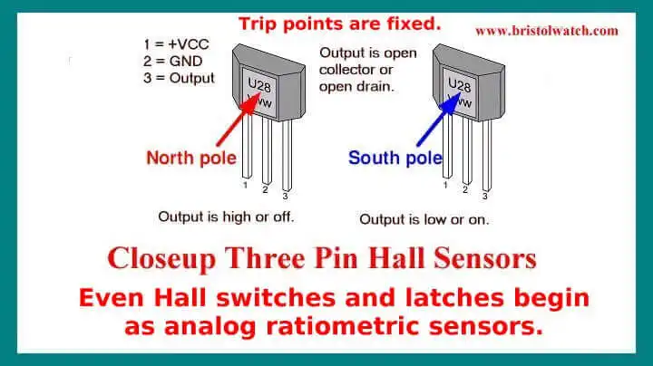
Both are unipolar devices one operating at 5-volts and the other at 12-volts respectively. With no magnetic field applied the output is about one-half the supply voltage.
The voltage will increase with the south magnetic pole on the face or decrease with the north magnetic pole on the face.
- YouTube videos:
- Basic Hall Effect Sensors YouTube
- Hall Effect Sensor Circuits YouTube
- Basics of Hall Effect Analog Sensors & Switches Pt. 1
- Operate, Build Hall Effect Switch Pt. 2
- Hall Effect Latches Theory and Circuits Pt. 3
The ratiometric Hall effect sensor is demonstrated in the latter third of the above video.
Spec sheets in PDF: TL173C and UGN3503.
Pictured above are typical pin outs on three lead Hall sensors. A ratiometric instead of switching on or off outputs a voltage from near zero to almost VCC proportional to the strength of the magnetic field and magnetic polarity.
Considering Magnets
The magnetic field typically produced by rare-earth magnets can be in excess of 1.4 teslas, whereas ferrite or ceramic magnets typically exhibit fields of 0.5 to 1 tesla. The Tesla is named in honor of the inventor, physicist, and electrical engineer Nikolai Tesla. A smaller magnetic field unit is the Gauss (1 Tesla = 10,000 Gauss):
10-9 - 10-8 gauss: the human brain magnetic field;
0.31-0.58 gauss: the Earth's magnetic field on its surface;
25 gauss: the Earth's magnetic field in its core;
50 gauss: a typical refrigerator magnet;
100 gauss: a small iron magnet;
2000 gauss: a small neodymium-iron-boron (NIB) magnet;
15,000-30,000 gauss: a medical magnetic resonance imaging electromagnet.
Above ref. Wiki. To find out more about rare earth magnets in general visit www.rare-earth-magnets.com. Magnets can be stacked (N to S) to form a more powerful magnet.
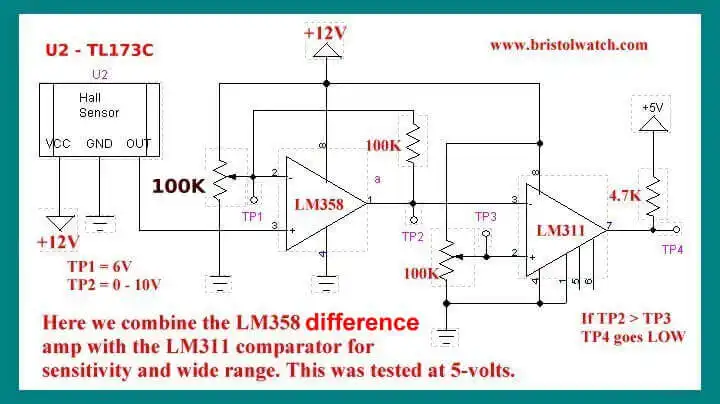
Let's consider the specifications for a Texas Instruments TL173C Hall sensor. At zero gauss the output is 6 volts. At 50 mT (1/1000th Tesla = 10 gauss or 500 gauss total) the output voltage is 7 volts. That is on the south pole of the magnet. At 50 mT. (500 gauss) the output voltage is 5 volts with the north pole.
Note that magnetic flux flows from north to south in conventional theory. Positive donates south, negative donates north. So -50 mT is -500 gauss north polarity.
We can also use electromagnets.
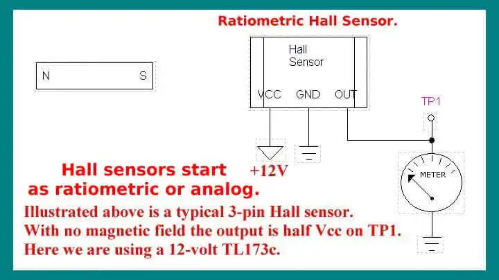
We can use the above circuit to read the output from the sensor. The voltage reading will give us an idea of the polarity and strength of a magnet. This opens the door to a number of interesting uses for these sensors. Let's look at a few.
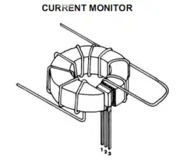
Calibrated linear Hall device in this example will measure the current through the wire. The higher the current the stronger the magnetic field and thus a higher output voltage.
Using a Comparator
Pictured above we have connected the sensor to a LM358 used as a difference amplifier feeding a LM311 comparator. We can adjust the potentiometers to set a trip point on the output . Unlike a standard Hall effect switch we can vary the sensitivity. The LM311 has an open collector output and can drive any number of small relays, opto-couplers, etc.
While this is a 12-volt circuit note the pull up resistor connected at TP4 connected to 5-volts.
Also see Voltage Comparator Information And Circuits
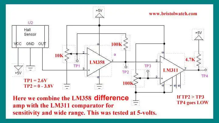
The circuit will also work at 5 volts as is, but use the UGN3503 or other 5-volt sensor instead. In the case of the UGN3503, disconnect it from the 5-volts and use 6 volts for greater sensitivity if desired.
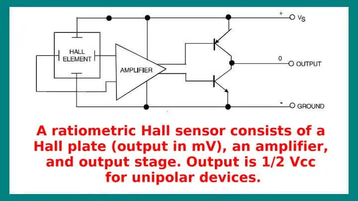
Inside a typical three-pin ratiometric Hall sensor.
- Hall Sensor with Alternating Current
- Using Hall Effect Switches and Sensors
- Using Ratiometric Hall Effect Sensors
- Hall Effect Sensors with the Arduino
- Quick navigation of this website:
- Basic Electronics Learning and Projects
- Basic Solid State Component Projects
- Arduino Microcontroller Projects
- Raspberry Pi Electronics, Programming
- Spec. sheets all PDF formate:
- UGN3013 Hall Switch (PDF file)
- TL173C 12-Volt Ratiometric Hall Sensor
- UGN3503 5-Volt Ratiometric Hall Effect Sensor
- Honeywell SS466 Hall Latch
Web site Copyright Lewis Loflin, All rights reserved.
If using this material on another site, please provide a link back to my site.