Fig. 1 Click for larger image.
Hall Sensor Circuits, Theory, Operation Part 2
by Lewis Loflin
Here I'll discuss theory of operation and uses of Hall sensors. I'll include magnetic "biasing" of Hall sensors to detect teeth in a gear or a gap or space in a gear.
We will also construct our own Hall latch and Hall switch, cover Schmitt trigger and comparator circuits.
While already widely used in automotive and industrial applications, Hall sensors are vital to the operation of new generation electric vehicles.
The electric vehicle industry is on the verge of a technological explosion.
See Introduction Hall Effect Switches Sensors Circuits Tutorial
Not the Same Old Hall Sensors
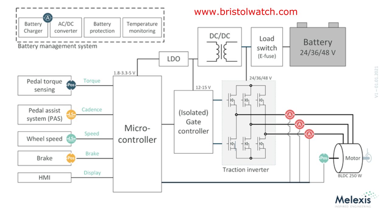
This Melexis Engineering electric car graphic illustrates where Hall sensors are used to detect peddle position, 3-phase motor winding current, motor rotation, wheel speed, etc.
In the past there were three types of Hall sensors. The most common were the ratiometric or analog output, the Hall switch, and the Hall latch.
The Hall switch and Hall latch are considered digital outputs that include an open-collector transistor.
I'm adding in two new definitions I'll will be introducing. One is the multi-Hall plate device with 2-to-4 or more Hall plates in a single package.
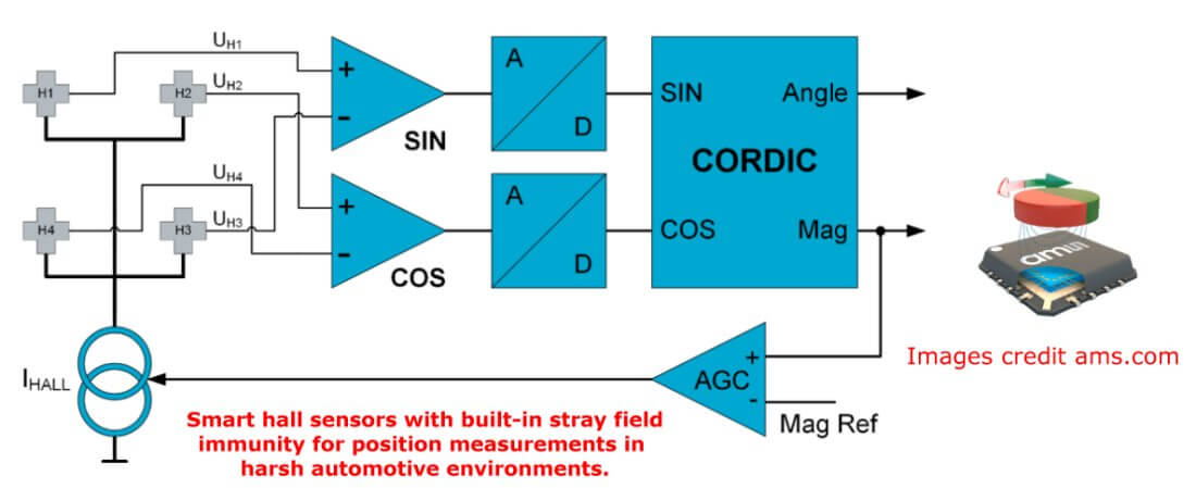
A good example are smart Hall sensors using 4 Hall plates from ams.com.
Another is the enhanced digital Hall devices some with multiple outputs while others are 2-wire digital devices that can even be programmed.
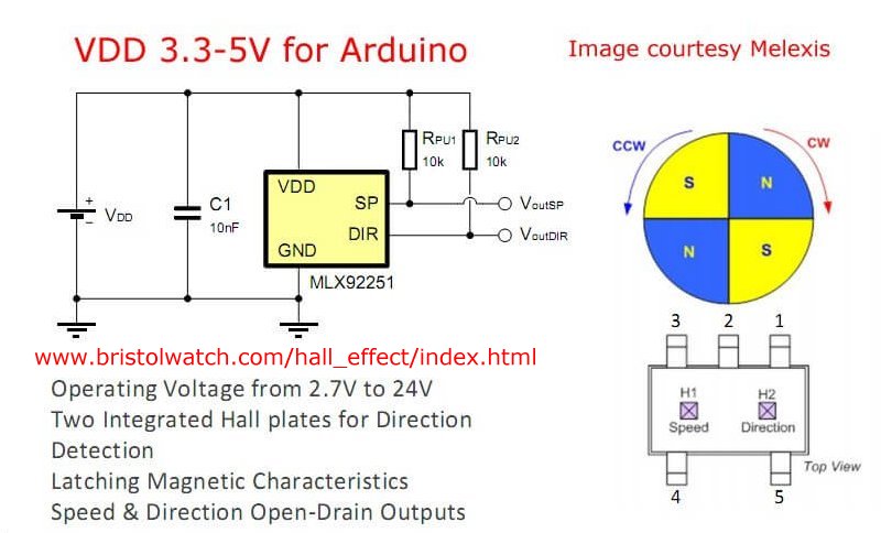
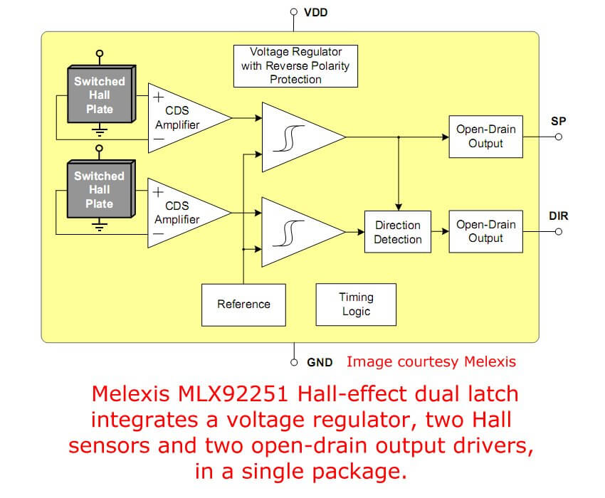
The Melexis MLX92251 has two-output open drain MOSFET outputs. It operates from 2.7V to 24V.
The Melexis MLX92251 block diagram illustrates two Hall plates and two outputs for speed and direction.
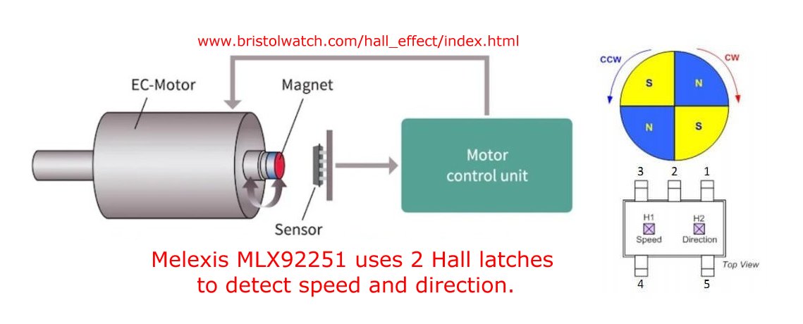
Motor using Melexis MLX92251 two output Hall sensor.
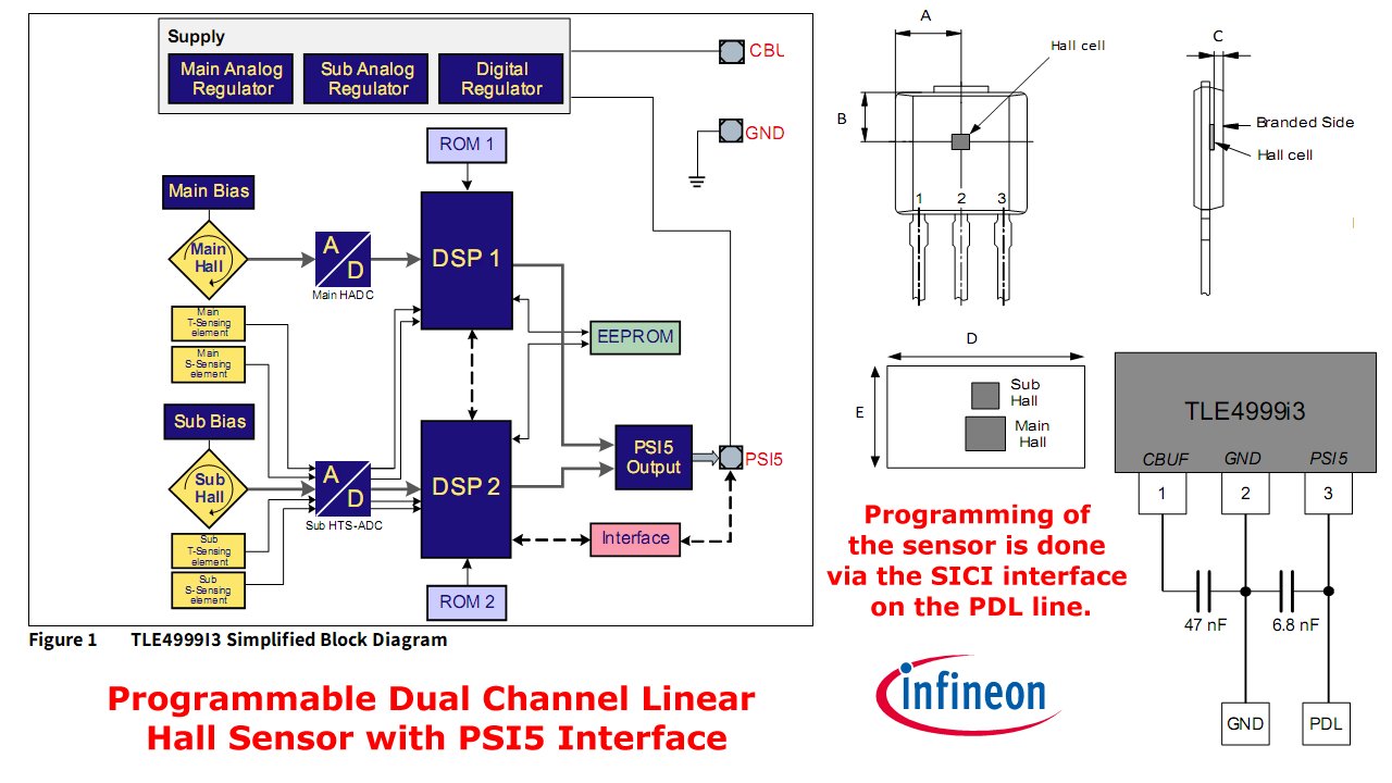
The Infineon TLE4999I3 is a "Programmable Dual Channel Linear Hall Sensor with PSI5 Interface."
The PSI5 Interface is defined as:
Peripheral Sensor Interface 5 (PSI5) is a bus interface used in automotive applications. It is an open standard which has been used for several years in airbag sensors. The interface offers highly reliable and fast data transmission.
In PSI5 communication, a current-modulated digital Manchester code is transmitted over a twisted pair cable. Since it is a current-modulated interface, it is highly resistant to EMI. In addition, a cyclic redundancy check detects errors in transmission. Up to three sensors can be connected on one PSI5 bus.
PSI5 offers secure data transmission and helps to reduce the size, weight and cost of a vehicle’s cable harness and connectors, and is therefore an excellent interface for automotive position-sensing applications.
Ref. ams.com.
Typical ratiometric Hall sensor is the Allegro A1301. It contains a Hall "plate" and a differential amplifier.
Plus the device has temperature and other compensation circuitry. A Hall sensor is better called an integrated circuit.
All Hall sensors including modern digital versions use a Hall plate plus a differential amplifier. The Hall voltage is very small often in micro-volts.
The Hall effect was discovered in 1879 years before the discovery of the electron in 1897.
While the effect is present in metals, today we use P-doped semiconductors such as indium antimonide, indium arsinide, gallium arsinide.
And yes, graphene. Graphene can be far more sensitive than other materials due to "very high carrier mobility at room temperature..."
To quote,
A breakthrough result on graphene Hall sensors was reported by a collaboration between the German company Bosch and scientists at the Max-Planck Institute. The sensitivity of a traditional silicon sensor is 70 V/AT, whereas their graphene Hall sensor has a sensitivity of 7,000 V/AT, which is 100 times more sensitive than an equivalent silicon device.
Ref. www.azonano.com April 4, 2022.
This detects magnetic fields in the nano-Tesla range while the Hall sensors we normally deal with operate in milli-Tesla or gauss range.
The Hall plate voltage output is a small analog voltage. Voltage polarity depends on the polarity of the magnetic field.
Let us clear up some definitions.
The south pole is considered a positive magnetic field. The north pole is considered a negative magnetic field. Magnetic flux is considered to flow from negative to positive.
In many specification sheets they use the terms unipolar and bipolar. This does not refer to power supply even though most sensors can use a bipolar supply, that is not what they refer to.
A unipolar Hall sensor refers to only 1 magnetic pole operates the sensor. This refers only to the single printed face of the package A Hall switch is a good example.
A Hall switch operates when a positive pole acts on the printed face. A negative pole does nothing.
A bipolar Hall refers to a Hall latch and perhaps a ratiometric sensor. With a Hall latch the south pole turns on the switch, the north pole turns off the switch.
Older material:
- Using Hall Effect Sensors with AC
- Using Hall Effect Switches and Sensors
- Ratiometric Hall Effect Sensors
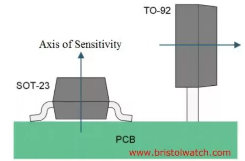
Fig. 2 Hall sensors "axis" of sensitivity examples.
Literature references the print face side of the sensor. But new Hall sensors place the Hall plate vertical to the printed face or even on the sides.
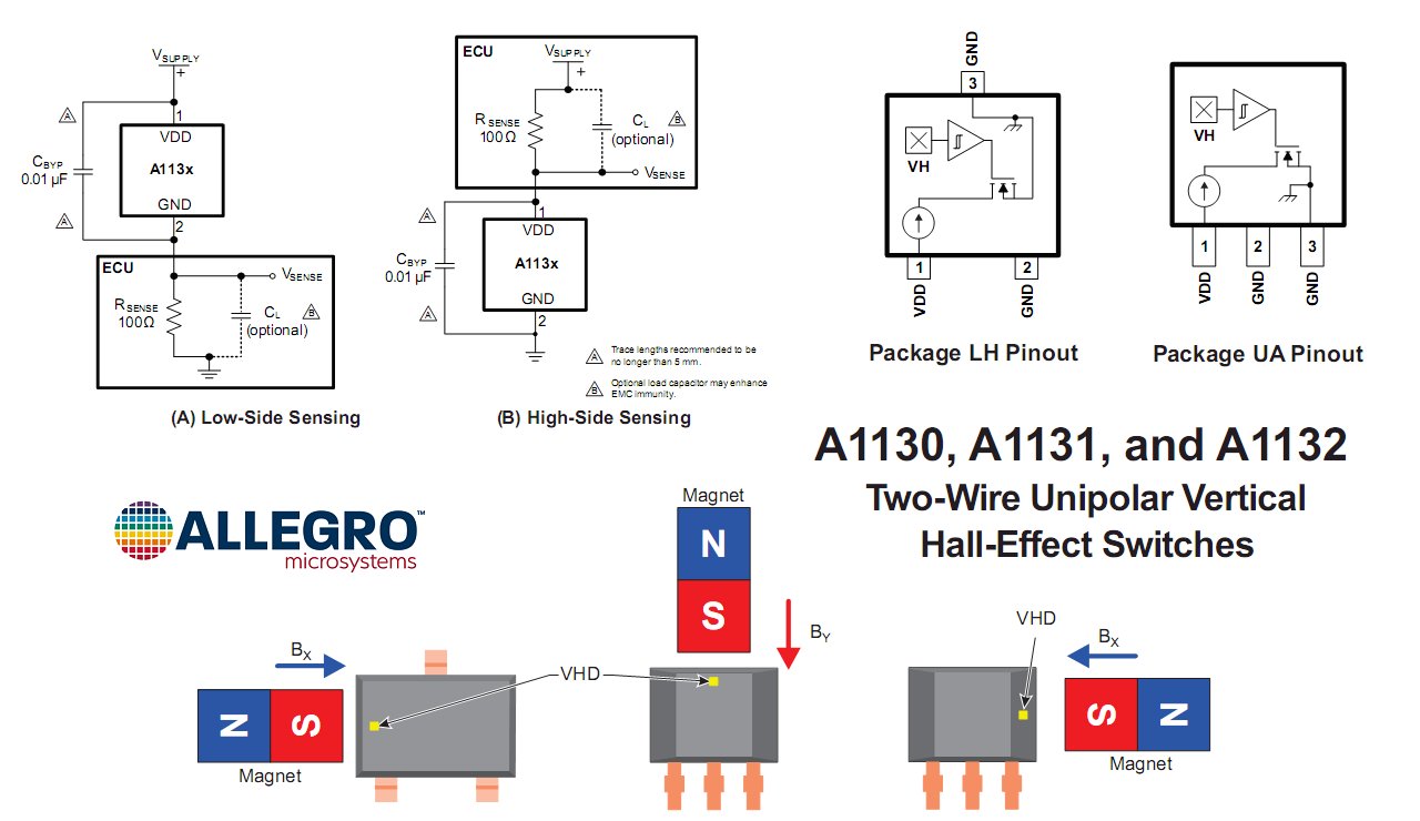
See Allegro A1130-32 Two-Wire Unipolar Vertical Hall Effect Switches
With a ratiometric sensor the output or VOUT increases/decreases depending on magnet strength, polarity, and distance from the Hall device.
With no magnetic field present VOUT = 2.5V assuming a 5-volt power supply. As the south pole approaches the printed face VOUT increases. I've never seen any sensor go to full VCC.
The north pole of the magnet on the printed side decreases VOUT all the way to zero if strong enough.
Note the non-printed face also works the same but opposite. The north pole increases VOUT.
Fig. 2 illustrates the "axis of sensitivity" where the magnetic field is perpendicular to the Hall plate. More below on this.
Note: there are Hall sensors known as "vertical" where the Hall plate is perpendicular to the TO-92 or other package. This enable the detection of a magnet from the side and not the front or back of the package.
See the following graphics:
This is also a two-wire device. Vertical only refers to the relation of the Hall plate.
The following are more examples of two-wire Hall sensors.
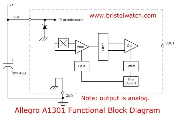
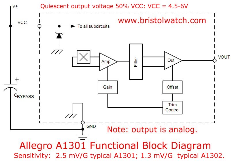
Fig. 3 Allegro A1301 Ratiometric Hall Sensor.
Typical are the A1301 and A1302 continuous-time, ratiometric, linear Hall-effect sensor ICs.
"They are optimized to accurately provide a voltage output that is proportional to an applied magnetic field. These devices have a quiescent output voltage that is 50% of the supply voltage. (VCC = 4.5V - 6V) Two output sensitivity options are provided: 2.5 mV/G typical for the A1301, and 1.3 mV/G typical for the A1302."
Note: 1 Tesla = 1000 mT; 1 mT = 10 gauss. A refrigerator magnet is ~100 gauss or 10 mT. An MRI machine magnet is 1-3 Tesla.
At 2.4mV/Gauss and 1.3mV/Gauss these are sensitive devices.
Source: A1301 spec sheet.
Now let us dig deeper into the Hall effect and associated circuits.
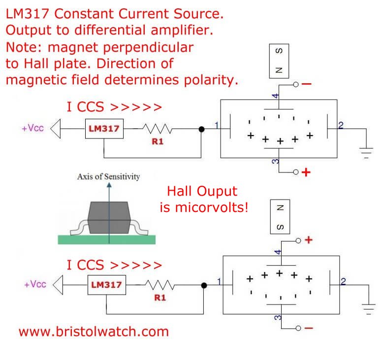
Fig. 4 Example Hall Sensor Plate with LM317 constant current source.
Click image for larger view.
Hall Sensors for Hobby Electronics
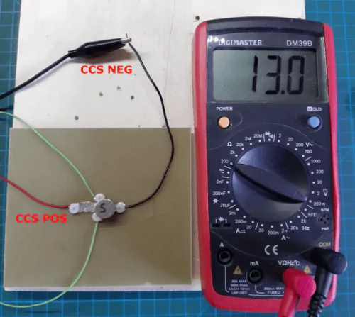
Don't recreate this. It is for illustration only. Also note Fig. 1.
Fig. 4 illustrates the voltage relationships in a Hall sensor "plate".
In my case I recreated an experiment from a college physics class. I made a Hall plate from bismuth metal I melted down with a heat gun. The resulting metal strip was brittle and required careful handling.
I used an LM317 constant current source I used in other projects to create a stable current through the bismuth strip.
Then I used a powerful neodymium magnet held perpendicular to the current flow. I created a small transverse voltage whose polarity depended on the magnetic polarity of the magnet.
A transverse voltage is defined as to quote,
..an electric current flows through a conductor in a magnetic field, the magnetic field exerts a transverse force on the moving charge carriers which tends to push them to one side of the conductor. This is most evident in a thin flat conductor ... A buildup of charge at the sides of the conductors will balance this magnetic influence, producing a measurable voltage between the two sides of the conductor. The presence of this measurable transverse voltage is called the Hall effect after E. H. Hall who discovered it in 1879.
Ref. http://hyperphysics.phy-astr.gsu.edu/hbase/magnetic/Hall.html
This voltage is very small in the micro-volts range and when I amplified it by 100 still came out to 8-12 mV.
See Crude Hall sensor made from thin sheet of bismuth metal.
See Melexis Engineering Hall Effect Graphic demonstrates a transverse voltage created by a magnet.
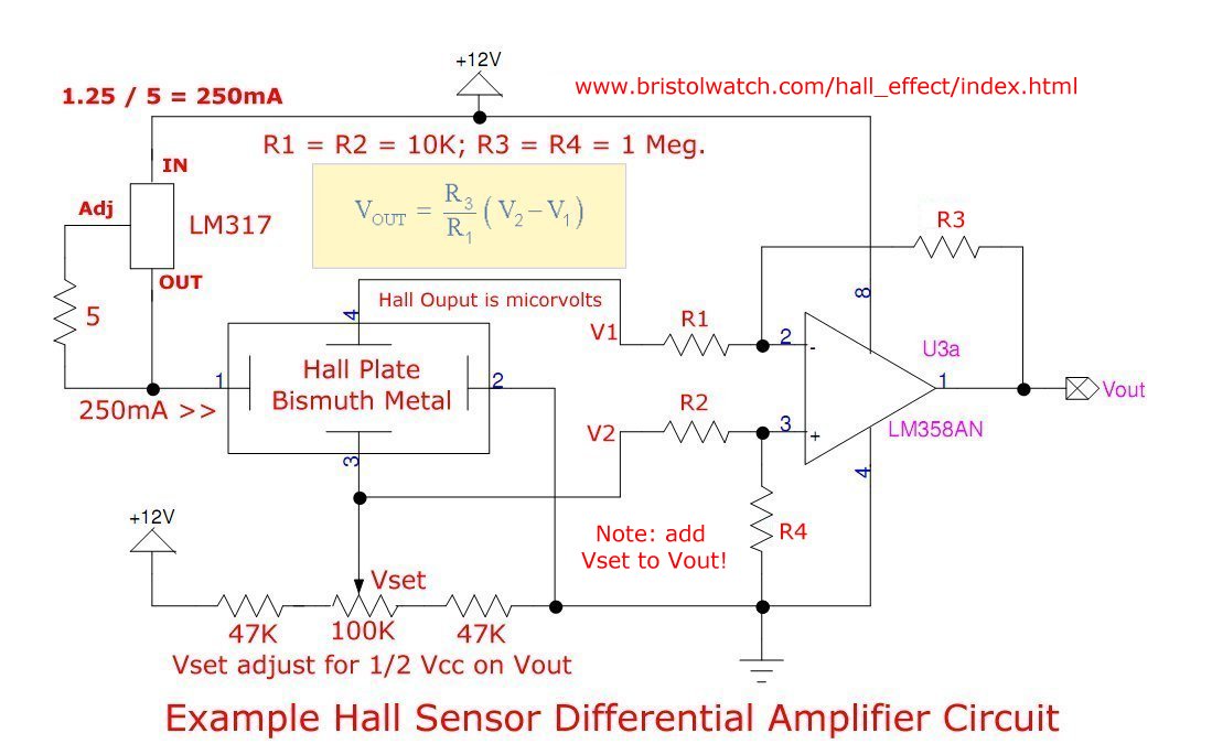
Fig. 5 Home built Hall circuit with differential amplifier using LM358.
Click image for larger view.
Fig. 5 is the bismuth Hall plate with an LM358 differential amplifier. Overall the circuit isn't practical and commercial units do a far better job.
This does illustrate the use of a differential amplifier I will be using elsewhere.

Fig. 5 Hall sensor uses gapped toroid to increase magnetic flux density.
Click image for larger view.
In figure 5 I'm using a gapped toroid to concentrate the magnetic flux from a conductor. The conductor could be a DC motor winding or power supply cable.
The magnetic flux is proportional to current flow, thus the output voltage (VOUT) of the Hall sensor is proportional to the magnetic flux thus current flow.
We can measure current flow based on the voltage level on VOUT of the Hall effect sensor.
We can also tell the direction of current flow. One direction is 2.5V to ~4.4V, the other direction 2.5V to 0V. I've never seen a Hall sensor go to full VCC.
We can also use a Hall switch where the output is on when enough current flow is present. The use of a Hall latch will also signal current flow, but will remain on until the current reverses.
So far I discussed the Allegro A1301 ratiometric Hall sensor. The voltage output is centered at 1/2 VCC, which at 5 volts is 2.5 volts, 6V at VCC = 12V.
Now let's look into a Hall switch and a Hall latch.
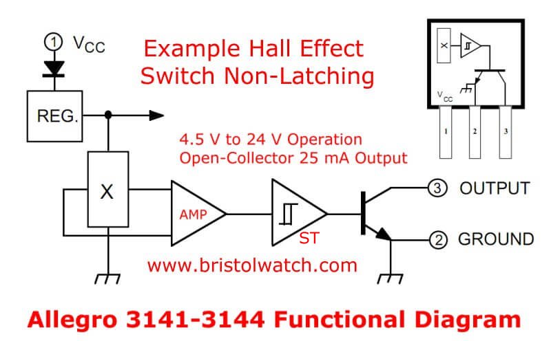
Fig. 6 Allegro A3141 Hall switch functional diagram.
Click image for larger view.
Hall Switch versus Hall Latch
Now we turn to Hall switches and Hall latches.
Both contain a Hall plate and an amplifier just like a ratiometric does.
Unlike the ratiometric Hall sensor they have added a Schmitt trigger and an open collector output transistor.
The transistor collector can be pulled up to VCC or even a differing voltage through a resistor.
The transistor doesn't handle a lot of current usually around 20mA. For higher power we can drive a PNP transistor.
See my graphic Honeywell SS466A Hall Effect Latch circuit connections. See circuit C.
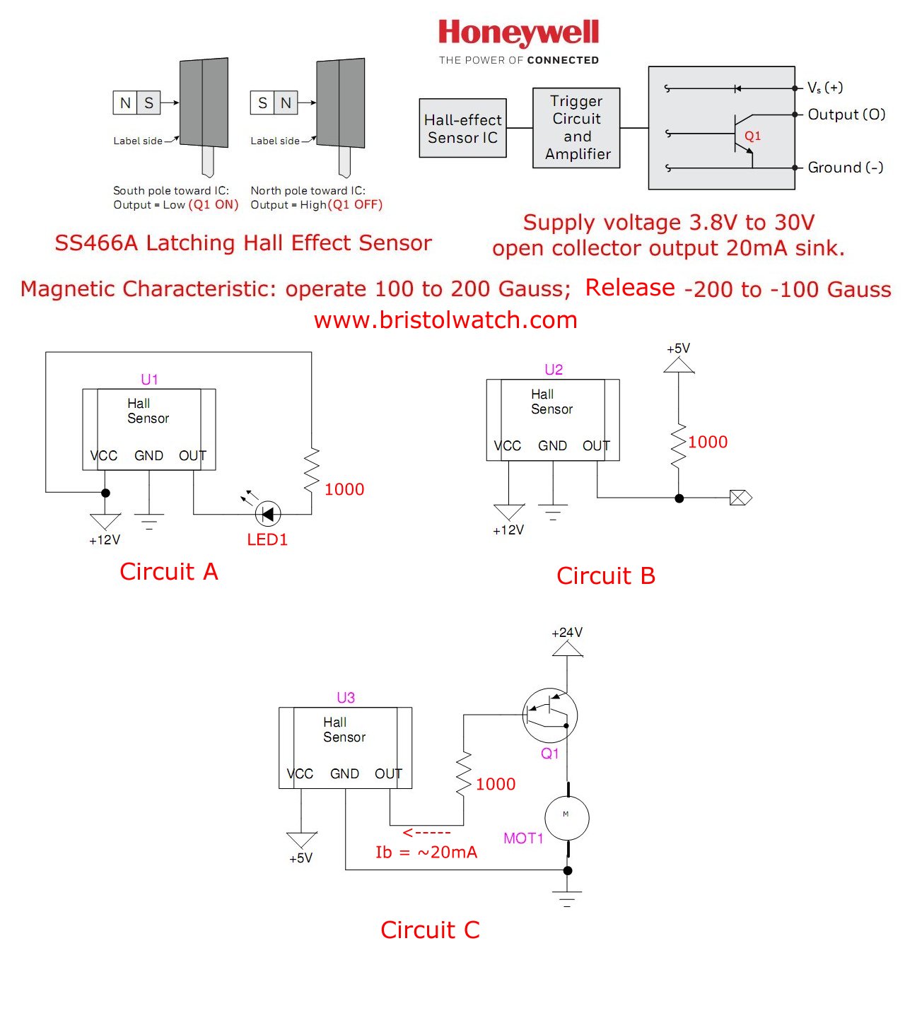
When a Hall switch or latch when turned on the transistor collector turns on or goes LOW. It switches to ground.
When the Hall switch/latch is turned off the transistor is turned off, the collector is HIGH or non-conductive.
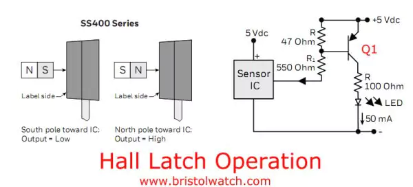
A Hall switch turns ON in the presence (south pole on the printed face) of a magnet. Remove the magnet the sensor turns off.
A Hall latch turns on just like the switch, but doesn't turn off when the magnet is removed.
One will have to use the opposite magnetic pole (north pole on the printed face) will turn the latch off.
The Hall switch and Hall latch differ in only one respect, the Schmitt trigger hysteresis.
Let's go back to the operation of a ratiometric Hall sensor. Hall switches and latches both have the Hall plate and the differential amplifier.
In the case of my test circuits I used 12 volts. With no magnetic field (0mT) on the Hall plate the differential amplifier output is biased for ~1/2 VCC.
Again a south (positive) magnetic field on the printed face the output voltage increases towards VCC. The north (negative) magnetic field the output voltage decreases towards zero.
This is an updated introduction to Hall sensors.
In our next section we use a ratiometric Hall sensor with a comparator to create a Hall switch and a Hall latch.
See LM311 Comparator Projects for Hobbyists Using Hall Sensors.
![]()
- Hall Sensor Circuits, Theory, Operation Updated 2022
- How Hall Effect Sensors Detect Ferrous Metals
- Exploring Omni Hall Effect Sensors with the TI DRV5032
- LM311 Comparator Projects Using Hall Sensors
- Hall Sensor with Alternating Current
- Using Hall Effect Switches and Sensors
- Using Ratiometric Hall Effect Sensors
- Hall Effect Sensors with the Arduino
- YouTube videos:
- Basic Hall Effect Sensors YouTube
- Hall Effect Sensor Circuits YouTube
- Basics of Hall Effect Analog Sensors & Switches Pt. 1
- Operate, Build Hall Effect Switch Pt. 2
- Hall Effect Latches Theory and Circuits Pt. 3
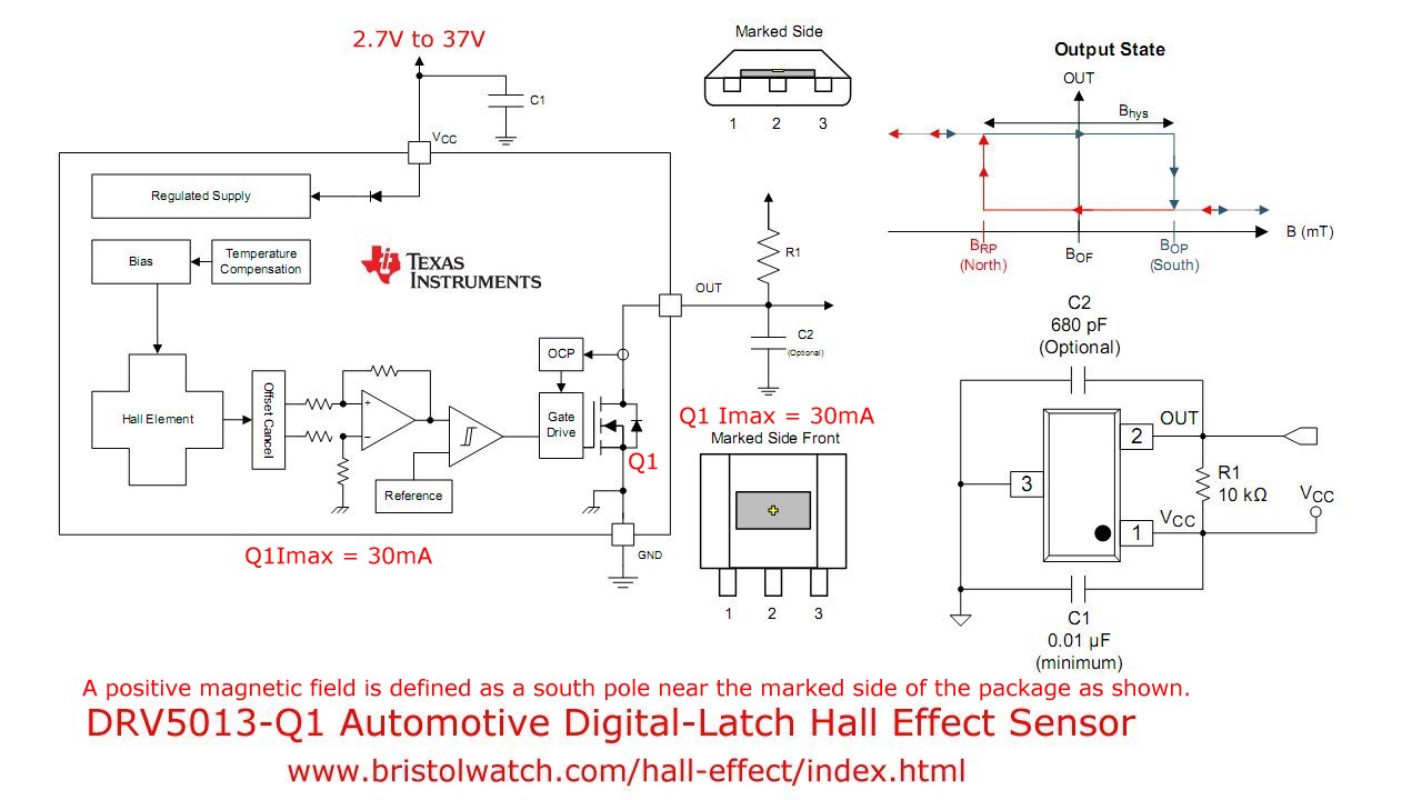
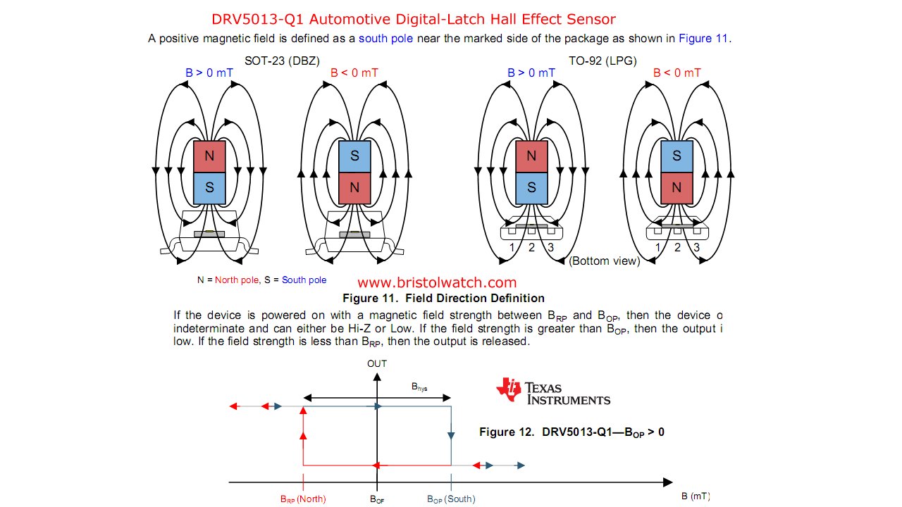
- DRV5013-Q1 Automotive Digital-Latch Hall Effect Sensor
- DRV5013-Q1 Hall Effect Sensor Magnetic Operation
- Comparator Circuits:
- Comparator Theory Circuits Tutorial
- Comparator Hysteresis and Schmitt Triggers
- Voltage Comparator Information And Circuits
- Looking at Window Comparator Circuits
- Photodiode Circuits Operation and Uses
- Photodiode Op-Amp Circuits Tutorial
- YouTube:
- Photodiodes and How they Work
- Photodiode Op-Amp Circuits
- Using Photovoltaic MOSFET Drivers
- YouTube:
- Comparator Circuits Introduction
Assorted images.
- Allegro 3141-3144 Hall Effect Switch
- Allegro A1130-32 Two-Wire Unipolar Vertical Hall Effect Switches
- Allegro A1301 Ratiometric Hall Sensor
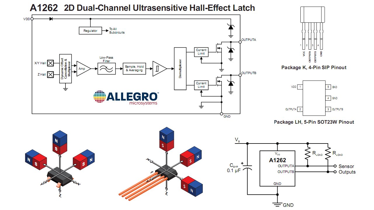
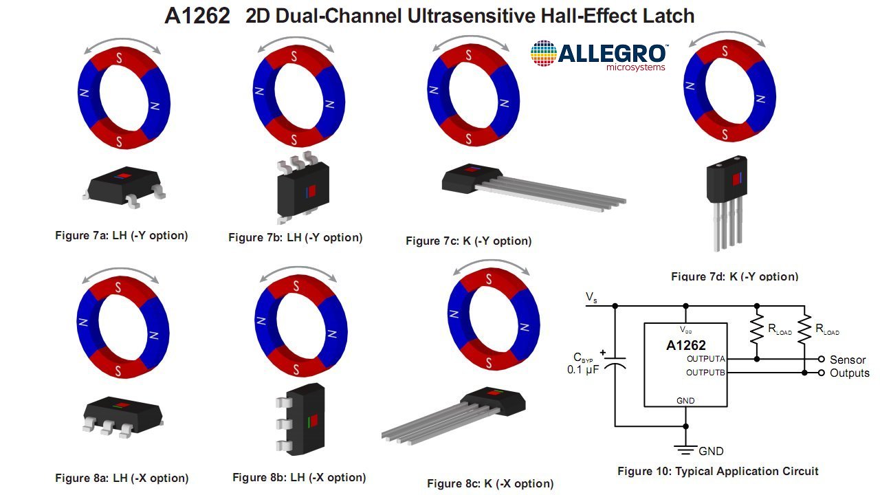
- Allegro A1262 2D Dual Channel Hall Effect Latch 1
- Allegro A1262 2D Dual Channel Hall Effect Latch 2
- Honeywell SS466A Hall Effect Latch
- Connections SS400 Series Hall Effect Latch
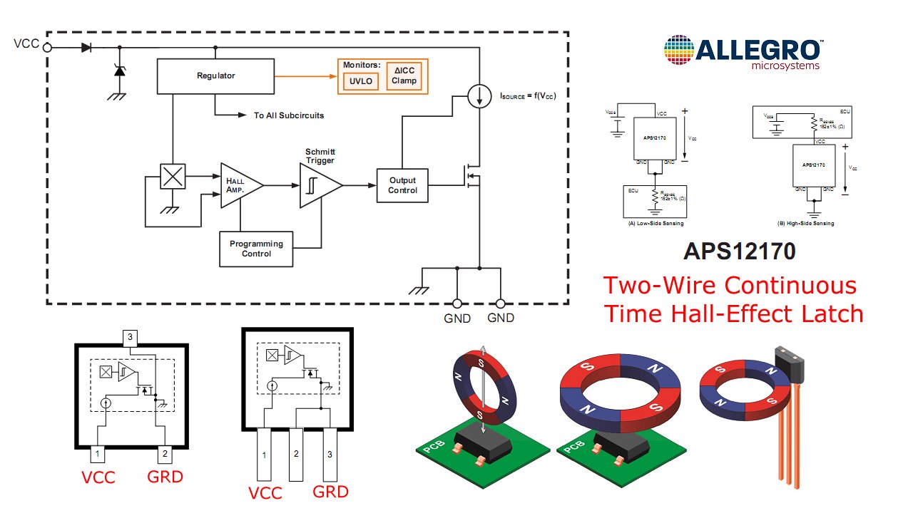
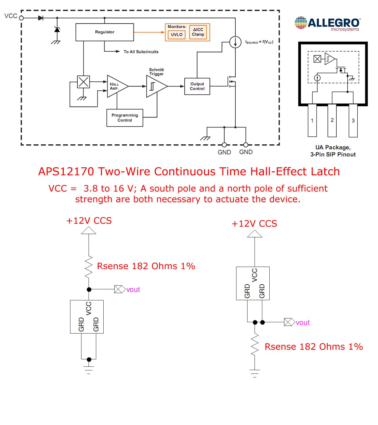
- Allegro APS12170 Two Wire Hall Effect Latch
- Allegro APS12170 Electrical connections.
- Hall Effect Sensors in Electric Vehicles
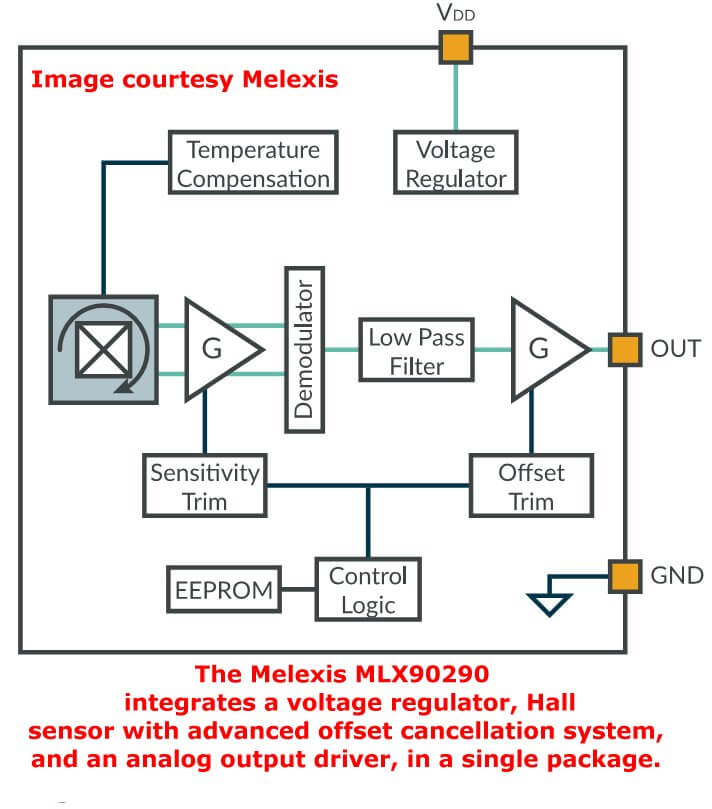
- Melexis MLX90290 Analog Hall Sensor Block Diagram
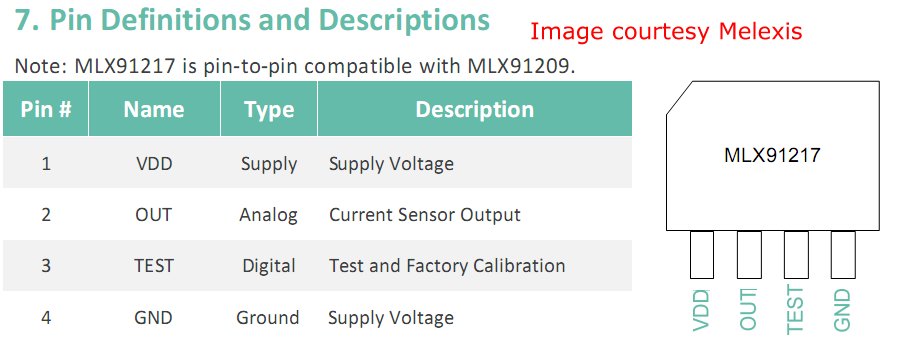
- Melexis MLX91217 Analog High Speed Current Sensor IC ±15 to ±450mT
- Melexis MLX91217 Block Diagram
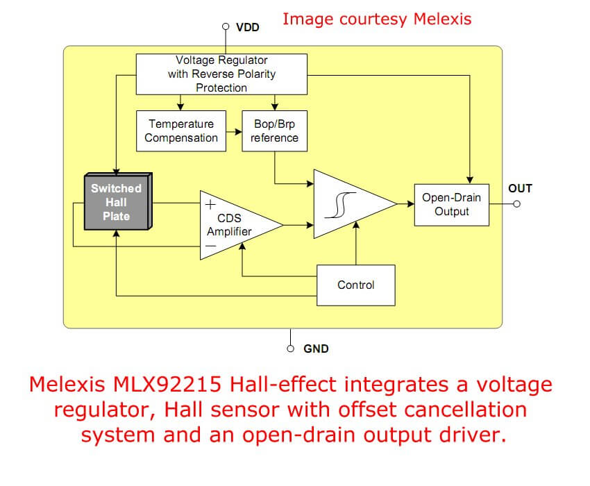
- Melexis MLX92215 3-Wire Hall Effect Latch 2.7V to 24V range
- Melexis MLX92251 Dual Hall Effect Latch with Speed & Direction Detection
- Melexis MLX92251 Block Diagram
- AMS Smart Hall Sensor with 4 Hall Plates
- Quick navigation of this website:
- Basic Electronics Learning and Projects
- Basic Solid State Component Projects
- Arduino Microcontroller Projects
- Raspberry Pi Electronics, Programming
- Spec. sheets all PDF formate:
- UGN3013 Hall Switch (PDF file)
- TL173C 12-Volt Ratiometric Hall Sensor
- UGN3503 5-Volt Ratiometric Hall Effect Sensor
- Honeywell SS466 Hall Latch
Web site Copyright Lewis Loflin, All rights reserved.
If using this material on another site, please provide a link back to my site.