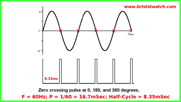
Fig. 1
Zero-Crossing Detectors Circuits and Applications
Updated circuits: Improved AC Zero Crossing Detectors for Arduino.
A zero-crossing detector is used to generate a sync pulse related to the AC voltage phase angle often used in power control circuits. Fig. 1 shows the relationship of a zero-crossing pulse to a sine wave. The pulse occurs at 0, 180, and 360 degrees.
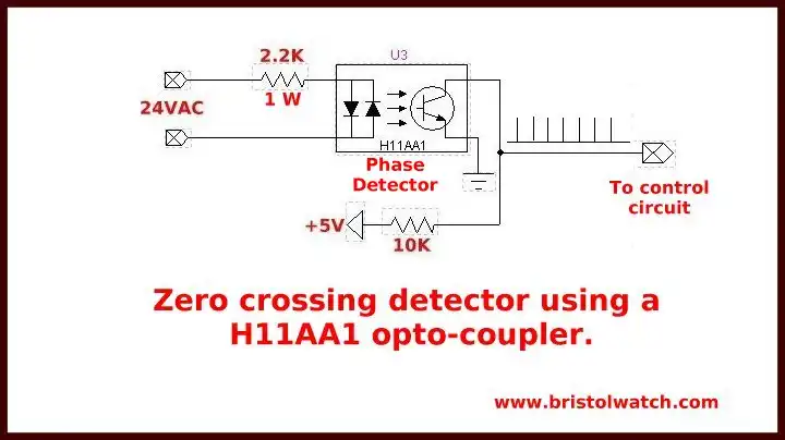
Fig. 2
Fig. 2 shows how to use a H11AA1 opto-coupler to generate a TTL level pulse. During most of the time the photo transistor output is LOW except when the voltage is near zero when the collector goes HIGH. The dual LED emitters of the H11AA1 assures both half-cycles are utilized.
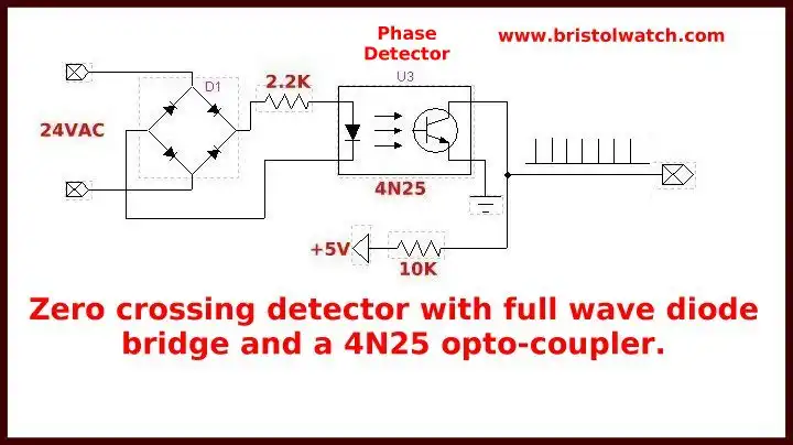
Fig. 3
Fig shows a more common opto-coupler such as a 4N25, but to use both half-cycles will require a diode bridge input.
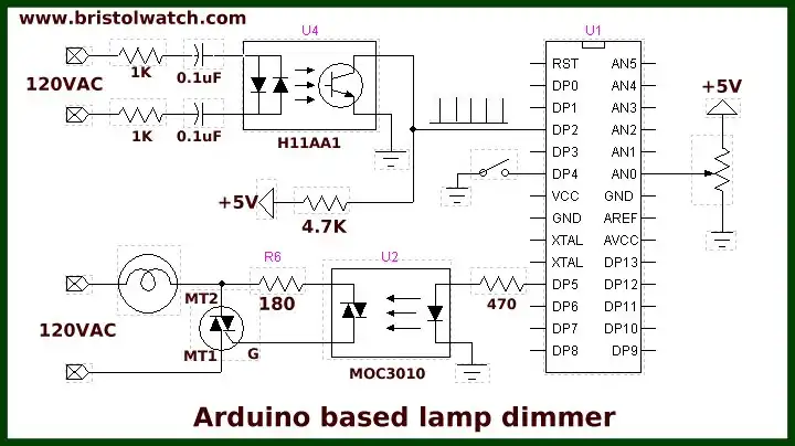
Fig. 4
Fig. 4 shows a direct application of a zero-crossing detector using an Arduino micro-controller to control the power output to a lamp. This variation still uses the H11AA1 but can be directly connected to 120VAC. The sketch is shown below.
The output of the H11AA1 is connected to Arduino DP2 to use its internal interrupt INTR0. When the switch on DP4 is closed a LOW is detected and the program connects interrupt 0 turning on a interrupt service routine acon.
The ISR reads the value of the potentiometer on AN0, divides by 4, then calculates a delay based on that value. The longer the delay (between 200uSec. and 8.3mSec.) the less power delivered to the load. The circuit will act as a lamp dimmer.
When the switch is opened the interrupt is detached and the lamp goes off. See the following related pages:
/*
Purpose: to detect zero crossing pulse at INT0 digital pin 2,
which after delay switches on  a triac.
Power activate by external switch
*/

#define triacPulse 5
#define SW 4
#define aconLed 13

int val;

void setup()  {
   pinMode(2, INPUT);
   digitalWrite(2, HIGH); // pull up
   pinMode(triacPulse, OUTPUT);
   pinMode(SW, INPUT);
   digitalWrite(SW, HIGH);
   pinMode(aconLed, OUTPUT);
   digitalWrite(aconLed, LOW);
  }

void loop() {
  // check for SW closed
  if (!digitalRead(SW))   {
    // enable power
    attachInterrupt(0, acon, FALLING);
    // HV indicator on
    digitalWrite(aconLed, HIGH);
  }  // end if
     else if (digitalRead(SW)) {
       detachInterrupt(0); // disable power
       // HV indicator off
       digitalWrite(aconLed, LOW);
     }  // else
  } // end loop


// begin ac int routine
// delay() will not work!
void acon()
   {
    delayMicroseconds((analogRead(0) * 7) + 200); // read AD1
    digitalWrite(triacPulse, HIGH);
    delayMicroseconds(50);
    // delay 50 uSec on output pulse to turn on triac
    digitalWrite(triacPulse, LOW);
   }
- Quick navigation of this website:
- Basic Electronics Learning and Projects
- Basic Solid State Component Projects
- Arduino Microcontroller Projects
- Raspberry Pi Electronics, Programming
- Using Zero-Crossing Detectors Power Control with Arduino
- Hardware Interrupts Demo for Arduino
- AC Power Control with Arduino
- AC Power Control Using Interrupts
- Zero-Crossing Detectors Circuits and Applications
- In Depth Look at AC Power Control with Arduino
- Hardware Interrupts Tutorial for Arduino
- Arduino AC Power Control Using Interrupts
- In Depth Look at AC Power Control with Arduino
- Basic Triacs and SCRs
- Solid State AC Relays with Triacs
- Light Activated Silicon Controlled Rectifier (LASCR)
- Digital Circuits:
- Simple Schmitt Trigger SN74HC14 Square Wave Generator
- Introduction to RC Differentiator Circuits and Uses
- SN74HC14 Square Wave Generator uses SN7476 JK Flip-Flop
- SN74C14 Three Output Pulse Generator Circuit
- Astable CD4047 Geiger Counter Power Supply
- CD4047 Monostable Multivibrator Circuit
- Basic TTL Tri-State Buffer Circuit Examples
- Tutorial NOR Gate SR Latch Circuits
- Tutorial NAND Gate SR Latch Circuit
- Tutorial OR-NOR Circuits Including Monostable Multivibrator
- Brief Tutorial of XOR and XNOR Logic Gates
- LM555-NE555 One-Shot Multivibrator AC Power Control
- YouTube:
- Three Output Digital Pulse Generator
- Digital Circuits:
- Two Transistor LED Flasher Circuit
- Astable CD4047 Geiger Counter Power Supply
- CD4047 Monostable Multivibrator Circuit
- Basic TTL Tri-State Buffer Circuit Examples
- Tutorial NOR Gate SR Latch Circuits
- Tutorial NAND Gate SR Latch Circuit
- Coils for Highly Selective Crystal Radio
- Neon (NE-2) Circuits You Can Build
- Understanding Xenon Flashtubes and Circuits
Web site Copyright Lewis Loflin, All rights reserved.
If using this material on another site, please provide a link back to my site.