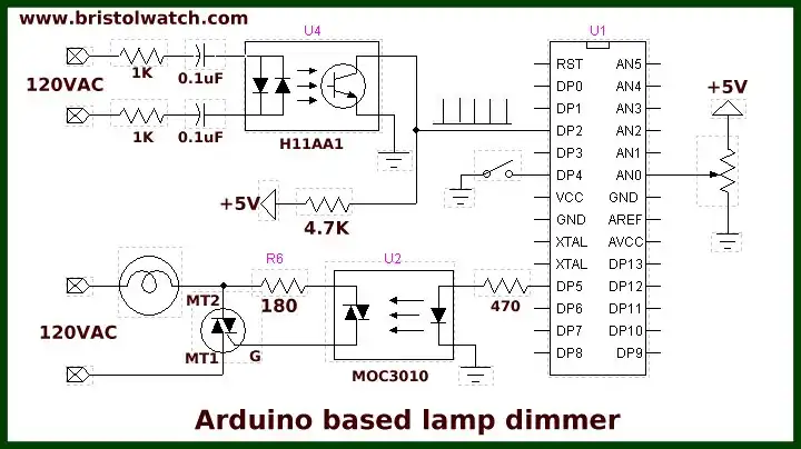
Fig. 1 Arduino with zero-crossing detector for AC power control.
Improved AC Zero Crossing Detectors for Arduino
For several years I have posted an Arduino based AC power control. The idea was an interrupt from a zero-crossing detector would be used with a delay program to fire a triac circuit.
By reading a potentiometer value the Arduino would calculate a delay on each AC half-cycle from 0 to 8.33 milliseconds. Longer the delay the less power delivered to the load. See Fig. 1.
The purpose here is to create a better zero-crossing detector. While the transistor out opto-couplers work the trigger pulse being somewhat distorted can cause problems.
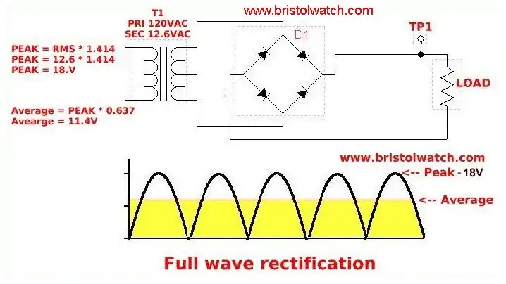
Fig. 2 Fullwave rectified AC to pulsating DC.
Fig. 2 illustrates the pulsating DC input to the opto-coupler LED(s).
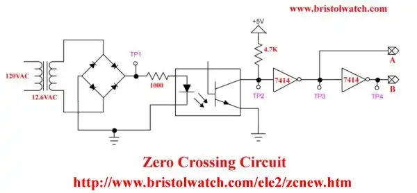
Fig. 3 Zero AC crossing detector improved with SN74LS14 Schmitt trigger inverters.
Fig. 3 illustrates a fullwave bridge rectifier and generic 4N24 opto-coupler. Here I have added two SN74LS14 Schmitt trigger inverters. This produces two clean output pulses at TP2 and TP3.
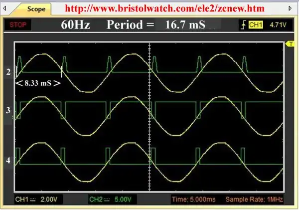
Fig. 4 Zero AC crossing detector improved with SN74LS14 Schmitt trigger waveforms.
Fig. 4 illustrates the output waveforms on my PC-oscilloscope. TP2 shows the poor waveform from the transistor collector circuit. TP3 illustrates a clean high-to-low pulse with about a 7% duty cycle.
TP4 we have a low-to-high pulse about a 7% cycle. All are 120Hz with a 8.33mS period.
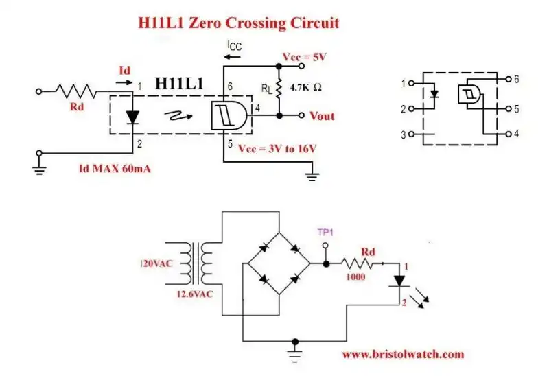
Fig. 5 Zero AC crossing detector using a H11L1 opto-coupler.
In Fig. 5 I have replaced the SN74LS14 Schmitt trigger inverters and the 4N25 optocoupler with a single H11L1 optocoupler circuit. Pin 4 is an open drain output with a pull up resistor. The H11L1 has internal Schmitt trigger and detector circuit. The voltage range on the output is 3 to 16 volts.
To quote the spec sheet:
"The H11L1 and H11L2 have a gallium arsenide Infrared LED optically coupled to a high–speed integrated detector with Schmitt trigger output. Designed for applications requiring electrical isolation, fast response time, noise immunity and digital logic compatibility."
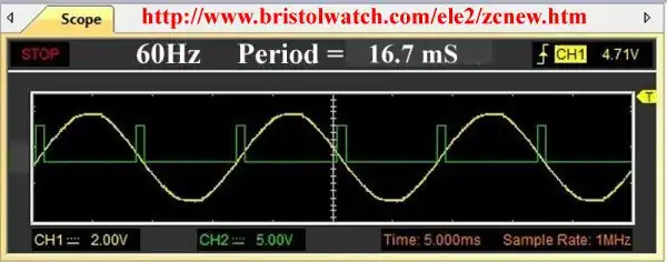
Fig. 6 Zero AC crossing detector using a H11L1 optocoupler waveform.
Fig. 6 illustrates the clean output pulse from pin 4. The duty cycle is about 7%, frequency is 120 Hertz and a period of 8.33 milliseconds.
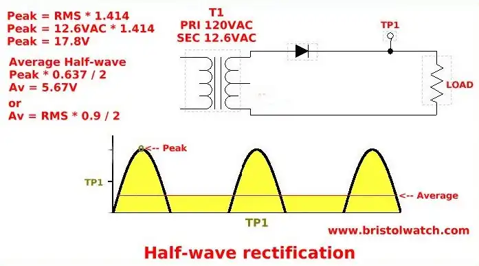
Fig. 7 Halfwave pulsating DC waveform.
This is halfwave pulsating DC. This is 60 Hertz with period of 16.7 milliseconds.
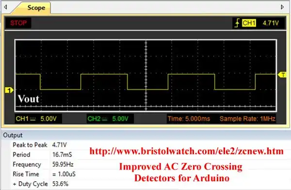
Fig. 8 H11L1 zero-crossing halfwave waveform output.
Finally the H11L1 output. This produces a 60 Hertz square wave with a 54% duty cycle. I would not use this for power control but to detect a falling or rising slope works fine.
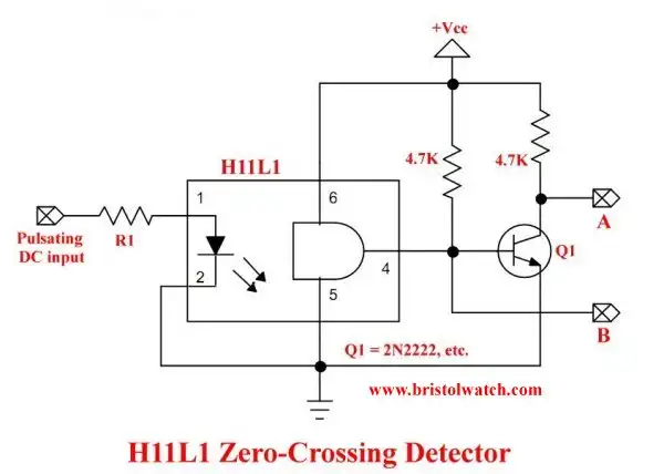
Fig. 9 another H11L1 zero-crossing circuit.
- Quick navigation of this website:
- Basic Electronics Learning and Projects
- Basic Solid State Component Projects
- Arduino Microcontroller Projects
- Raspberry Pi Electronics, Programming
- Using Zero-Crossing Detectors Power Control with Arduino
- Hardware Interrupts Demo for Arduino
- AC Power Control with Arduino
- AC Power Control Using Interrupts
- Zero-Crossing Detectors Circuits and Applications
- In Depth Look at AC Power Control with Arduino
- Hardware Interrupts Tutorial for Arduino
- Arduino AC Power Control Using Interrupts
- In Depth Look at AC Power Control with Arduino
- Basic Triacs and SCRs
- Solid State AC Relays with Triacs
- Light Activated Silicon Controlled Rectifier (LASCR)
- Digital Circuits:
- Simple Schmitt Trigger SN74HC14 Square Wave Generator
- Introduction to RC Differentiator Circuits and Uses
- SN74HC14 Square Wave Generator uses SN7476 JK Flip-Flop
- SN74C14 Three Output Pulse Generator Circuit
- Astable CD4047 Geiger Counter Power Supply
- CD4047 Monostable Multivibrator Circuit
- Basic TTL Tri-State Buffer Circuit Examples
- Tutorial NOR Gate SR Latch Circuits
- Tutorial NAND Gate SR Latch Circuit
- Tutorial OR-NOR Circuits Including Monostable Multivibrator
- Brief Tutorial of XOR and XNOR Logic Gates
- LM555-NE555 One-Shot Multivibrator AC Power Control
- YouTube:
- Three Output Digital Pulse Generator
- Digital Circuits:
- Two Transistor LED Flasher Circuit
- Astable CD4047 Geiger Counter Power Supply
- CD4047 Monostable Multivibrator Circuit
- Basic TTL Tri-State Buffer Circuit Examples
- Tutorial NOR Gate SR Latch Circuits
- Tutorial NAND Gate SR Latch Circuit
- Coils for Highly Selective Crystal Radio
- Neon (NE-2) Circuits You Can Build
- Understanding Xenon Flashtubes and Circuits
Web site Copyright Lewis Loflin, All rights reserved.
If using this material on another site, please provide a link back to my site.