Fig. 1
Simple 2 Transistor LED Flasher Circuit
by Lewis Loflin
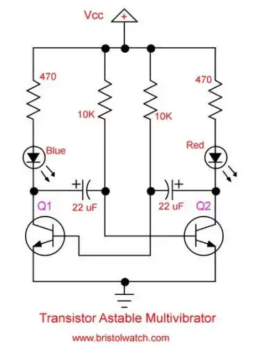
Here is a blast from past as they say with a transistor astable multivibrator. While today most people use a NE555 timer IC this version is simple to build. The LEDs altering on/off cycle whose flash rate is control by the two 22uF capacitors and the two 10K resistors.
Let's assume Q1 is turned off the collector rises to Vcc on the positive plate of the 22uF capacitor. During this time no current flow through the blue LED and it's turned off. At the same time Q2 is turned on and the red LED is turned on.
The two 22uF capacitors enter an altering charge-discharge cycles creating two square waves on the collectors that are 180 degrees out of phase. The flash rate is determined by the capacitor values and the two base charge resistors.
To get the Period:
P = t1 + t2 = 0.69R1C1 + 0.69R2C2 = (10,000 * .000022) + (10,000 * .000022) * 0.69= 0.3036 Sec.
Frequency = 1 / P = 1 / 0.3036 = 3.3 Hz.
The above formula assumes C1 = C2 and the capacitor value is converted to Farads. Another formula for frequency is:
f = 1 / P = 1 / 1.38RC = 1 / 1.38 * 10,000 * .000022 = 1 / 0.3036 seconds = 3.3 Hz.
In the video I used 5V and 12V and the change in voltage I observed no change in the rate of the LEDs on/off cycle. I'm sure it has some minor effect. The two transistors are NPN types and should be the same type. I used two TIP41A.
Note the capacitor and resistor values don't have to be the same. For example one capacitor can be 22uF and another 100uF where one LED stays on longer than the other.
- Operation switching power supplies and transformer connection tutorials:
- Generating High Voltage with an Inductor
- Arduino Buck Switching Voltage Regulator Demo Only
- Switching Regular Configuration Review
- LM2575 Simple Switching Voltage Regulators
- Voltage Buck-Boost Transformer Connections Tutorial
Other Circuits
- Hall Effect Magnetic Switches and Sensors
- Transistor-Zener Diode Regulator Circuits
- Build an Adjustable 0-34 volt power supply with the LM317
- Coils for Highly Selective Crystal Radio
- Neon (NE-2) Circuits You Can Build
- Understanding Xenon Flashtubes and Circuits
Web site Copyright Lewis Loflin, All rights reserved.
If using this material on another site, please provide a link back to my site.