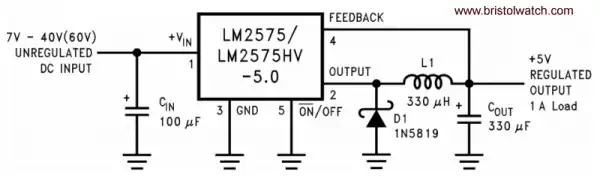
Fig. 1 LM7525T fixed 5-volt regulator.
LM2575 Simple Switching Voltage Regulators
by Lewis Loflin
For the electronics hobbyist tackling switching voltage regulators can be daunting. They can be complex and touchy to build. Here I'll be looking at simple switching voltage regulators based on 5-pin LM25XX series manufactured by a number of companies. They come in both fixed and variable voltages. The LM2575T is rated at 1 amp while the LM2596T is rated at 3 amps.
Fig. 1 show the LM2575-5 fixed 5-volt regulator. It consists of only 4 external components with a voltage input range up to 60 volts. All of these are "buck" voltage step down regulators.
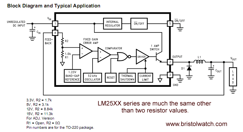
The internal block diagram consists of a 52KHz oscillator, 1.23V precision voltage reference, error amp, thermal shutdown and current limit. Both the fixed and adjustable versions are the same other than two internal and/or external resistors.
Cin is an input bypass low ESR capacitor used to bypass spikes and noise to prevent them form effecting the output. L1 and Cout form both a filter and energy storage "tank" circuits whose voltage output is determined by the duty cycle of the pulse-width modulated output from the LM25XX. Feedback from the output to pin 4 regulates the duty cycle to maintain a fixed output voltage.
D1 is referred to as a "catch" diode that transfers energy from L1 during PWM off time to Cout. This diode must be a high-speed Schottky type diode. A 1N4001, etc. rectifier diodes will not work. The current and voltage rating of D1 depends on the output voltage and current.
To minimize switching noise and voltage spike short leads and a heavy ground plane are essential in all switching power supplies. Using good quality low ESR capacitors also help. I have found myself with the capacitors larger values seem to work fine.
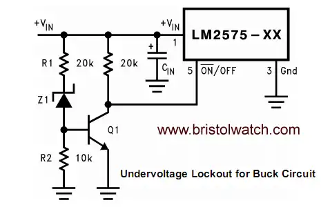
Fig. 2 LM75XX under voltage lockout.
An additional feature is pin 5 can be used by a micro-controller to turn the device on or off. Zero volts or a digital LOW turns the unit on and is often tied to ground otherwise. Fig. 2 illustrates a basic under voltage lockout circuit.
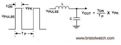
Fig. 3 LM2575 PWM versus voltage output.
See Pulse Width Modulation Power Control.
All switching regulators have two basic modes of operation: continuous and discontinuous. The difference between the two types relates to the inductor current, whether it is flowing continuously, or if it drops to zero for a period of time in the normal switching cycle. Each mode has distinctively different operating characteristics, which can affect the regulator performance and requirements.
The LM2575 (or any of the Simple Switcher family) can be used for both continuous and discontinuous modes of operation. With relatively heavy load currents, the circuit operates in the continuous mode (inductor current always flowing), but under light load conditions, the circuit will be forced to the discontinuous mode (inductor current falls to zero for a period of time). This discontinuous mode of operation is perfectly acceptable. For light loads (less than approximately 200 mA) it may be desirable to operate the regulator in the discontinuous mode, primarily because of the lower inductor values required for the discontinuous mode.
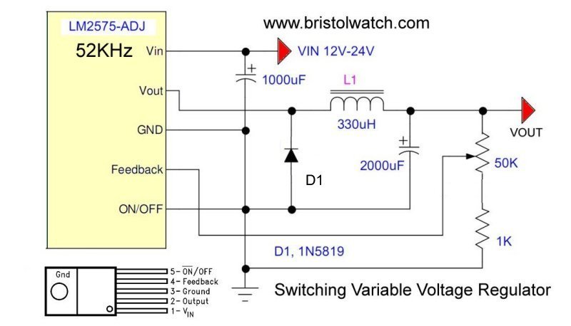
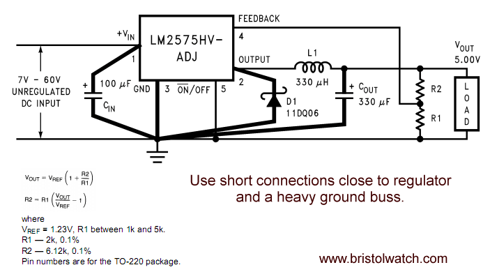
Fig. 4 LM2575-ADJ variable voltage regulator.
When should one use a switching regulator?
If the input voltage for a 5-volt or 3.3 volt at under 400mA I'd use a LM7805 or similar series type non-switching regulator. But going from 24V to volts means 75% or more of the energy will be wasted as heat requiring large heat sinks, etc. it's a matter of cost versus efficiency. I measured a 82% efficiency going from 17V to 5V with a my LM2575-ADJ circuit (Fig. 4) that allows me to select any voltage within reason. Using larger capacitors doesn't hurt at all.
- Operation switching power supplies and transformer connection tutorials:
- Generating High Voltage with an Inductor
- Arduino Buck Switching Voltage Regulator Demo Only
- Switching Regular Configuration Review
- LM2575 Simple Switching Voltage Regulators
- Voltage Buck-Boost Transformer Connections Tutorial
- Using TL431A Li-Ion Battery Charger Tutorials
- TL431A Lithium-Ion Cell Charging Circuits
- Charging Multi-Cell Lithium-Ion Battery Packs
- TL431 Over-Voltage, Under-Voltage Detector Circuits
- TL431A Constant Current Source Working Circuits Demo
- Power TL431 Constant Current Source Circuits
Other Circuits
- Hall Effect Magnetic Switches and Sensors
- Transistor-Zener Diode Regulator Circuits
- Build an Adjustable 0-34 volt power supply with the LM317
- Coils for Highly Selective Crystal Radio
- Neon (NE-2) Circuits You Can Build
- Understanding Xenon Flashtubes and Circuits
Web site Copyright Lewis Loflin, All rights reserved.
If using this material on another site, please provide a link back to my site.