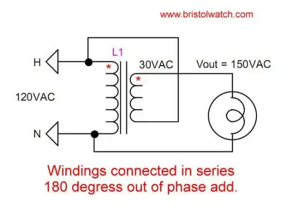
Fig. 1
Voltage Buck-Boost Transformer Connections Tutorial
by Lewis Loflin
Caution: there is no high voltage isolation in this circuit could result in electrical shock. The current is limited by the wire smallest gauge. This is for informational purposes only and comes with no warranty.
Here I'll illustrate transformer voltage buck or boost connections. This is where we connected the secondary of a power transformer in series with the primary winding to increase voltage output (boost) or reduce voltage output (buck). Please note there's no longer electrical isolation between the primary and secondary and could cause an electrical shock.
This forms a type of autotransformer with a single winding made from 2 windings in series.
When AC transformer windings are connected in series the phase relationship will determine if the voltages add or subtract. When a voltage is induced in a transformer winding the phase is 180 degrees out of phase with the voltage that created it. In the example in Fig. 1 the dots donate those two connections that are in phase with each other.
Fig. 1 the connection from the top of the primary 120V winding to out of phase bottom of the 30V winding causes the voltage to add. 120VAC + 30VAC = 150VAC. This is the boost connection.
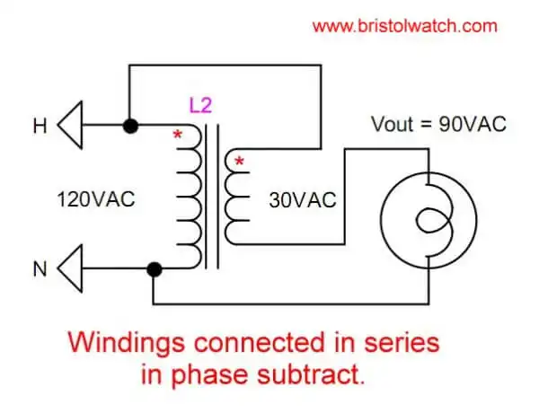
Fig. 2
In Fig. 2 the top of the primary winding is connected in phase with the secondary winding known as the "buck" or subtract configuration. 120VAC - 30VAC = 90VAC.
It's that simple. This completes a brief look at boost-buck transformer connections.
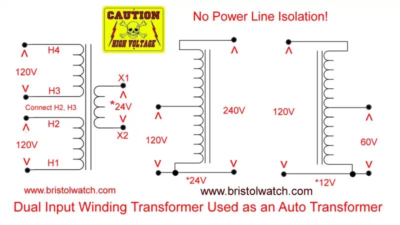
Fig. 3 Dual primary transformer connected as an autotransformer.
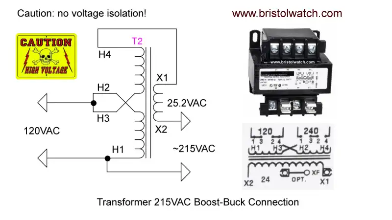
Fig. 4 Power transformer connected in voltage boost-buck or subtract configuration.
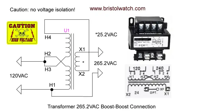
Fig. 5 Power transformer connected in voltage boost-boost or add configuration.
- Basic Power Transformers
- Connecting Transformers in Series-Parallel
- Voltage Buck-Boost Transformer Connections Tutorial
- Connecting Industrial Control Transformers Examples
- Operation switching power supplies and transformer connection tutorials:
- Generating High Voltage with an Inductor
- Arduino Buck Switching Voltage Regulator Demo Only
- Switching Regular Configuration Review
- LM2575 Simple Switching Voltage Regulators
- Quick navigation of this website:
- Basic Electronics Learning and Projects
- H-Bridge Motor Controls
- Transistor Switching Circuits
- Power Supplies Projects
- Switching Power Supply Projects
- Battery Chargers with Arduino Controller
- Opto-Coupler, SCR, and Triac Circuits AC Power Control
- Zero-Crossing Detectors for AC Power Control with Arduino
- DIACs, SIDACs, and Unijunction Transistors Switching Circuits
- Xenon Flash Tube Circuits - High Voltage!
- Hall Sensors Circuits and Sensors for Magnetic Detection
- Comparator Circuit Examples
- Constant Current and Current Limiter Circuits
- Photo Diode Detector Circuits
- Digital Circuits and Projects
- Stepper Motor Operation and Control
- Crystal Radio, Odds and Ends Circuits
- Geiger Counters and Science Topics
- Popular Webpages & Corresponding Videos
- YouTube Videos List
- Off Site:
- Bristolblog an Alternative News Skeptic Site
- Web Master
- Tri-Cities VA-TN
- General Science
- US Constitution
- Christianity 101
- Religious Themes
Web site Copyright Lewis Loflin, All rights reserved.
If using this material on another site, please provide a link back to my site.