Python Programming PC Printer Port Hardware Interfacing
For an updated and better way to program a printer port see the following:
Here we will learn how to use the IBM PC printer port to control external hardware.
While the Raspberry Pi is the rave for learning Python and interfacing hardware, a much better alternative is sitting in most people's closets.
The IBM PC has been around close to three decades and most older machines have a printer port. This can be tapped into to control external hardware in DOS, Windows, and Linux. I've even used it under GW Basic and Borland C++ for DOS.
DOS is long gone, Windows XP forward is a mess, but Linux is here to stay.
Using a Python module known as pyparallel we can access the 17 I/O pins on the printer port connector. This includes an 8-bit output data port, five individual input lines and four additional output lines. These are all at standard TTL 5-volt levels so we don't deal with the 3-volt mess from Raspberry Pi.
The advantage over the Raspberry Pi is a more powerful real computer, more I/O, 5-volt TTL level inputs/outputs, real data storage, and greater computing power. There are even modules to allow use of I2C which I won't go into.
(Above) Here in this series we will learn how to read an external analog voltage and operate a LCD display by using python's bitwise operators.
In using an older PC or even a new one I employ the very same fast desktop system I created for the Raspberry Pi and the setup of the system is nearly identical. Another advantage is these machines include real serial ports which we can use with python pyserial.
I stayed with Debian based distributions and chose light weight systems such as Sparky Linux or Chrunchbang. The screens look and operate identical to my Raspberry Pi system.
In fact the Python programs I wrote for this with modifications will work on Raspberry Pi as far as the hardware interface. I design my programs to work across multiple platforms with minimal use of special libraries.
I'll assume the user has some knowledge of Linux but I'll walk the process through step by step. Read how to setup Raspberry Pi on my website for more information on Linux.
In this demo I used a circa 2002 Dell Optiplex Gx50 with 512K of RAM. It worked a little better than Raspberry Pi. I chose this obsolete machine to demonstrate how to reuse an older computer.
Setup for use of parallel port under Python
Update August 2104: a Linux live DVD is now available to allow one to experiment and use the programs presented here without installation to one's computer.
See Live Linux Distro for Using Printer Port with Electronics
Check to see if /dev/parport0 exists with your file manager. If it isn't there then "sudo modprobe ppdev". This is default with most 2.6 and later Linux kernels. Now it should be present.
To have ppdev loaded on bootup (if you had to load it) do the following with your favorite text editor:
$ sudo leafpad /etc/module Add "ppdev" save and close.
Next we must gain access to the parallel port by removing module lp:
$ sudo rmmod lp Open the following with a text editor such as leafpad:
$ sudo leafpad /etc/rc.localAdd before 0: "rmmod lp" save and close.
That will remove module lp on bootup.
Next one will still need to be a member group lp if it's there:
$ sudo adduser whoever lp Even if the module is removed to allow access to the parallel port one must still be a member of group lp or operate as root.
Reboot the machine log back in.
Issues with the software
First issue is when pyparallel-0.2.zip is downloaded from www.sourceforge.com and unzipped the install will fail.
The software is just plain screwed. I managed to find the correct setup file elsewhere and got it to work and include that in my corrected version for download from my website. Do the following from a terminal (must have internet connection):
$ mkdir pport $ cd pport $ wget http://www.bristolwatch.com/pport/tar/pport.tar.gz $ tar -zxvpf pport.tar.gz Then:
$sudo python setup1.py install The Printer Port Connector
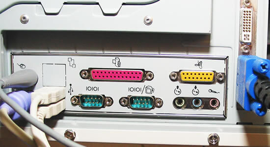
Let's take to look at the pins available on the printer port.
Note: This will not work with PC port adaptors.
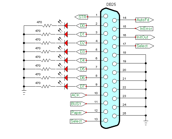
The connector is known as a Db25. This consists of one 8-bit data port, 5 input "status" pins and 4 output "control" pins.
These are all 5-volt TTL level signals so we aren't dealing with this 3-volt problem and a level converter like in the Raspberry Pi.
The spec sheets show several pins have level inversion, that is a HIGH will read LOW and vice-versa. That is taken care of in the software so don't sweat it. Pin labeling is a little different depending on what spec sheet or website we get it from.
Note that the four output pins could be open collector - I have never found this on my computers.
Pin functions:
1   Strobe   ---> output
10  ACK      <--- input
11  BUSY     <--- input
12  Paper    <--- input
13  Select   <--- input

14  LF       ---> out also called auto feed
15  Error    <--- input
16  RESET    ---> output also called INIT
17  SEL PRI  ---> output also called select
Pins 2-9 correspond to data port D0-D7
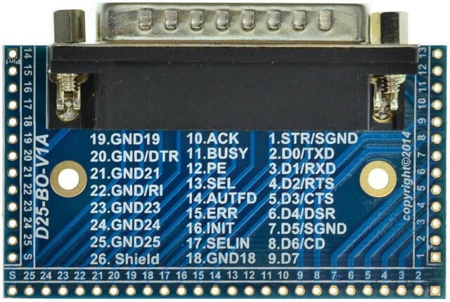
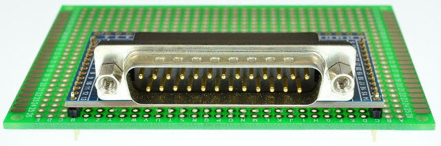
To connect the printer port to a prototyping board there's plenty of options from building your own to buying a breakout board as pictured pport2.jpg. I've done both and buying an inexpensive adaptor board saves a lot of time and can reduce errors preventing damage to the port which can't be repaired. That's why I said use an older computer to start with.
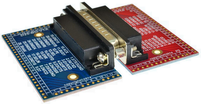
More views of the adaptor pport1.jpg, pport3.jpg, pport4.jpg, and pport5.jpg.
Don't overlook inexpensive breakout boards offered on Ebay for use with CNC machines!
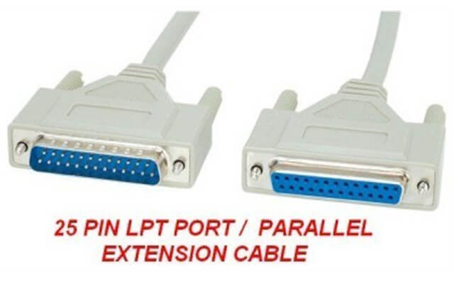
Pictured pportx.jpg is a DB25 connector cable. Caution: do not use a cable made for transferring data between two PCs. They look the same but it won't work!
Short Introduction
Note the PC port doesn't include a 5-volt power supply and one must use an external supply. Don't exceed 5 volts!
With the 8 LEDs connected start python on the command line and enter the following:
>>> import parallel
>>> p = parallel.Parallel()     #open LPT1
>>> p.setData(0x55)
Assuming one has 8 LEDs connected to the data port pins 2-9 (through a resistor to ground) 4 LEDs should be on. (D0, D2, D4, D6) The data port value can be from 0 to 255 but will be in binary format on the LEDs.
It's easy to use idle for python programming if one is using Debian. Ubuntu, etc. Otherwise open the following with a text editor such as leafpad or beaver:
$ leafpad count.py This will produce an empty file - copy and past the following code then save as count.py in the pport directory you created earlier:
#!/usr/bin/env python

import parallel
import time

p = parallel.Parallel()

# Count 0-255 binary on 8 LEDs

for var in range(0,256):
    p.setData(var)
    print var
    time.sleep(.5) #delay 500 mSec.

p.setData(0x00) # turn LEDs off

print "Good by!"

exit
Save and exit the editor.
Type "ls" and make sure the file count.py can be seen. Then type the following:
$ python count.py The program will print the count from 0 to 255 on the terminal and display the value in binary on the 8 LEDs. When reaching 255 the program will turn all the LEDs off, print "Good by!" and exit the program.
Notice the first line "#!/usr/bin/env python". This tells the system to execute the file using python. To do that we must make file count.py executable:
$ chmod +x count.py Now one doesn't have type python simply:
$ ./count.py One can even rename the file count.py to leave off the .py:
$ mv count.py count Then type ./count and it will work as before.
If one wants to execute "count" anywhere do the following:
$ sudo mv count /usr/local/bin Then type "count" on any terminal and the program will run.
Download pport-1.0.iso from Sourceforge.com then burn to DVD (file size 920 meg.), insert into DVD drive and reboot. Make sure PC is set to boot from DVD ROM.
This is pre-configured by myself to use Python to control the printer port. Python can be run from IDLE or Geany.
All of my PPORT electronics projects will work without installation to a PC.
Programs can be saved to thumb drive in LIVE mode.
Projects
Below are listed a series of projects using pyparallel and electronics. Starting with routines I wrote to aid students I'd advise walking through this in sequence. Have fun and send comments and/or corrections to lewis@bvu.net.
- Introduction to Python Bitwise Operations
- Python Bitwise Operations by Example
- Using the PC Printer Port series:
- Programming the PC Printer Port in Python
- Additional Commands for Py-Parallel
- Controlling Data Bits on the PC Parallel Port
- Connecting Switches to the PC Printer Port with Python
- Reading an Analog Voltage Through the PC Printer Port Part 1
- Reading an Analog Voltage Through the PC Printer Port Part 2
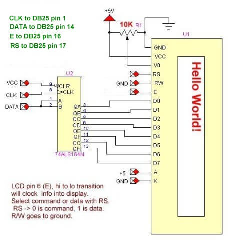
- Controlling a Serial LCD Display on a PC Printer Port with Python
- Serial ADC and LCD Display with PC Printer Port with Python
- Controlling MAX7219 LED Display with PC Printer Port with Python
- MAX7219 8-Digit LED Display and Serial ADC in Python
- Project pages:
- Part 1: Read Arduino with PC Printer Port
- Part 2: Better way to Read Arduino Through the PC Printer Port
- Part 3: Read-Write an Arduino Through a PC Printer Port
- Part 4: Control LCD Display and Arduino from the PC Printer Port
- Arduino sketches needed by programs:
- pportArduino1.ino read only after reset.
- pportArduino2.ino reset once and multiple reads.
- pportArduino3.ino reset once read write Arduino infinite times - multiple commands.
- Related Raspberry Pi projects:
- Connect Serial LCD to Raspberry Pi
- Serial Read from Arduino to Raspberry Pi
- Arduino Raspberry Pi Interface with LCD Display
Linux Videos
- Live Linux Distro for Using Printer Port with Electronics
- Using the powerful Rox-Filer system in Linux
- Use FEH under Linux for a Wallpaper Setter
- How to create Symbolic links in Linux
- Printer Port Interfacing Videos:
- Connect Electronics to PC printer Port with Python
- Setup PC Printer Port with Python-Linux
- Use PC Printer Port to Read Analog Voltage
- Read-Write Arduino ADC PWN with Printer Port
- Printer Port to Serial LCD Display
- Connect Arduino to PC Printer Port for advanced control
Printer Port in C
- Exploring Digital Computer Electronics
- Hardware Review Connecting PC Parallel Ports
- Operation TB6600 Stepper Controller with PC Parallel Port
- Build or Buy Parallel Port Breakout Board?
- Build Serial HD44780 LCD Display Connect to Parallel Port
- Motherboards
- Presario 1999 CM1001 Gaming Computer Salvage
- Live Test 2002 VIA EPIA-800 Mini ITX Motherboard
- Salvage, Test 2012 AAEON EMB-B75A Industrial Motherboard
- Web Master
- Gen. Electronics
- YouTube Channel
- Arduino Projects
- Raspberry Pi & Linux
- PIC18F2550 in C
- PIC16F628A Assembly
- PICAXE Projects
Web site Copyright Lewis Loflin, All rights reserved.
If using this material on another site, please provide a link back to my site.