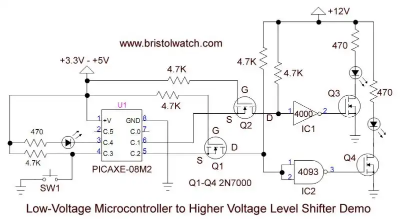
Fig. 1
Interfacing Microcontrollers to CMOS and MOSFET Circuits
by Lewis Loflin
Fig. 1 illustrates connecting a 5-volt microcontroller to a 12-volt MOSFET switch.
Q1 and Q2 are N-channel 2N7000 MOSFETs. The CD40106B is a HEX inverter circuit using only 2 of the six available inverters. It will replace the CD4000 and has Schmitt trigger inputs.
The CD40106B +Vcc is connected to +12-volts (pin 16) and ground (pin 8) are not shown. The four unused inputs should go to ground.
The CD40106B has Schmitt trigger inputs.
A LOW output from the PICAXE is inverted to HIGH on the MOSFET gate turning on the MOSFET.
Also in Fig. 1 one can one of four 2-input NAND gates from a CD4093B. This acts as a Schmitt trigger inverter.
Note that Q1 and Q3 work as a non-inverting voltage interface. What if one needs an inverting input? Fig. 2 below does just that.
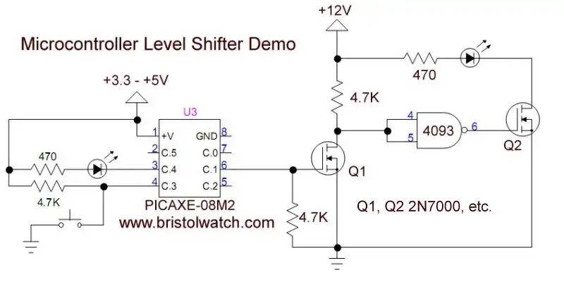
Fig. 2
Below is a simple program for the PICAXE-08M2 used in the video.
#picaxe 08m2 ; type chip used

symbol LED1 = C.1
symbol LED2 = C.2

LOW LED1
HIGH LED2

main:
toggle LED1
toggle LED2
pause 500
goto main

- MOSFET-Transistor Drivers with TC4420 and TC4429, IGBTs, etc.
- Introduction TC4420-TC4429 MOSFET Drivers
- Use TC4420 MOSFET Driver for Simple H-Bridge Circuit
- TC4420 MOSFET Driver Various Circuits
- TC4420 MOSFET Driver Replacement Circuits
- Test Power MOSFET Transistors, IGBTs
- Insulated Gate Bipolar Transistor IGBT Circuits
- Issues on Connecting MOSFETs in Parallel
- TC4420 MOSFET Driver Replacement Circuits
- TB6600 Stepper Motor Driver with Arduino
- Interfacing Microcontrollers to CMOS and MOSFET Circuits
- Simplified CMOS-MOSFET H-Bridge Circuit
- Tri-State H-Bridge using CD4093B CMOS Circuit
- Common Collector Opto-Isolated Bipolar Transistor Switches
- Compare 2N3055 MJE10005 Transistor Power Switches
- Connecting PCF8574P GPIO Expander to Raspberry Pi
- Programming PCF8574P 8-bit I-O Expander with Arduino
- DS1307 RTC with a CD4040 as a Precision Time Base
- CD4040 12-stage Binary Counter with DS1307 RTC Time Base
- Pt. 1 Interfacing Microcontrollers to CMOS and MOSFET Circuits
- Pt. 2 Simplified CMOS-MOSFET H-Bridge Circuit
- Pt. 3 Tri-State H-Bridge using CD4093B CMOS Circuit
- Pt. 1 TB6600 Stepper Motor Driver with Arduino
- Pt. 2 Program TB6600 Stepper Motor Driver with Arduino
- TB6600 Stepper Motor Driver with Arduino
- Off Site:
- Web Master
- Tri-Cities VA-TN
- General Science
- Hobby Electronics
- US Constitution
- Christianity 101
- Religious Themes
© Copyright 2018 Lewis Loflin E-Mail