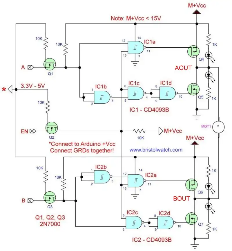
Fig. 1
Tri-State H-Bridge using CD4093B CMOS Circuit
by Lewis Loflin
Here we look at an improved tri-state H-bridge. This a big improvement over earlier variations.
The goal is circuit theory. To connect to basic microcontrollers operating at 3.3V-5V to a flexible higher voltage circuit.
The voltage range of the circuit based on a CD4093B and an IRF4905 (Q4, Q6) and IRFZ44N (Q5, Q7) MOSFETs ~3-15-volts.
The Schmitt trigger inputs of the CD4093B quad, 2-input NAND gate assures more stable switching. This replaces the CD4011B from earlier circuits.
Q1, Q2, and Q3 are 2N7000 N-channel MOSFETs in a TO-92 package. With their associated 10K pull up resistors provide an easy voltage interface between the microcontroller and CD4093B switching the power MOSFETs Q4-Q7.
This replaced the SN7407 TTL integrated circuit from earlier designs. This also eliminated the use of opto-couplers.
Connections "A" and "B" with "EN" connect directly to the microcontroller or Raspberry Pi IO pins.
Make sure to connect the ground to the microcontroller ground. Connect "*" to the microcontroller 3.3V or 5V power buss.
When "EN" is HIGH motor direction is determined by inputs "A" and "B". The can be connected together and programmed for forward and reverse only. "EN" acts as motor ON-OFF.
As a final note the "EN" connection my require a 1K resistor to ground. This assures the motor is turned off if the IO pin to the Raspberry Pi, etc. isn't LOW during boot up.
- From Basic Digital Circuits to H-Bridge Motor Controls
- Non-Inverting Tri-State Buffer-Switch Demo Circuit
- Review Connecting Digital Logic and Transistors
- Optocouplers for TTL-CMOS Logic Level Shifting
- H-Bridge Schematic with MOSFET Outputs
| EN | Input A | Input B | AOUT | BOUT | OUT MODE |
| HIGH | HIGH | LOW | 12V | 12V | STOP |
| HIGH | HIGH | HIGH | 12V | 0V | FWD |
| HIGH | LOW | HIGH | 0V | 0V | BRK |
| HIGH | LOW | LOW | 0V | 12V | REV |
| LOW | X | X | HiZ | HiZ | OFF |
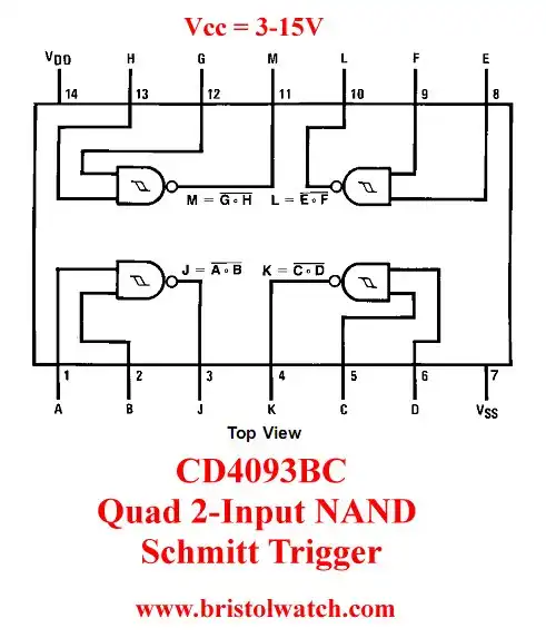
Fig. 2
CD4093B Quad 2-Input NAND Schmitt Trigger is shown in Fig. 2. Voltage range 3-15-volts. While low power the current sink or source output is low. But this no problem driving MOSFET transistors.
The Schmitt trigger input assures better circuit performance in H-bridge circuits. There is better noise response.

- MOSFET-Transistor Drivers with TC4420 and TC4429, IGBTs, etc.
- Introduction TC4420-TC4429 MOSFET Drivers
- Use TC4420 MOSFET Driver for Simple H-Bridge Circuit
- TC4420 MOSFET Driver Various Circuits
- TC4420 MOSFET Driver Replacement Circuits
- Test Power MOSFET Transistors, IGBTs
- Insulated Gate Bipolar Transistor IGBT Circuits
- Issues on Connecting MOSFETs in Parallel
- TC4420 MOSFET Driver Replacement Circuits
- TB6600 Stepper Motor Driver with Arduino
- Interfacing Microcontrollers to CMOS and MOSFET Circuits
- Simplified CMOS-MOSFET H-Bridge Circuit
- Tri-State H-Bridge using CD4093B CMOS Circuit
- Common Collector Opto-Isolated Bipolar Transistor Switches
- Compare 2N3055 MJE10005 Transistor Power Switches
- Connecting PCF8574P GPIO Expander to Raspberry Pi
- Programming PCF8574P 8-bit I-O Expander with Arduino
- DS1307 RTC with a CD4040 as a Precision Time Base
- CD4040 12-stage Binary Counter with DS1307 RTC Time Base
- Pt. 1 Interfacing Microcontrollers to CMOS and MOSFET Circuits
- Pt. 2 Simplified CMOS-MOSFET H-Bridge Circuit
- Pt. 3 Tri-State H-Bridge using CD4093B CMOS Circuit
- Pt. 1 TB6600 Stepper Motor Driver with Arduino
- Pt. 2 Program TB6600 Stepper Motor Driver with Arduino
- TB6600 Stepper Motor Driver with Arduino
- Off Site:
- Web Master
- Tri-Cities VA-TN
- General Science
- Hobby Electronics
- US Constitution
- Christianity 101
- Religious Themes
© Copyright 2018 Lewis Loflin E-Mail