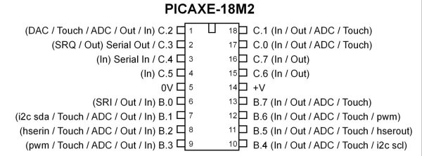
Fig. 1 PICAXE 18M2.
PICAXE Arduino IO Ports Tutorial
All micro-controllers must connect to something to be of any use and how that is done is the subject of this tutorial. While I will use the PICAXE 18M2 the material here will apply to any other micro-controller. In Figure 1 is the pinout of the 18M2 chip. The function of most pins can be changed under software control making available any number of configurations. Here I'll explore input, output, and analog-to digital conversion. (ADC)
I'll assume standard 5-volt digital logic where electrically a "HIGH" (or binary 1 or set condition) is 5 volts while "LOW" or zero volts is an electrical connection to ground, which is the negative side of the power supply. There is a third state for digital logic known as "floating" that is simply connected to nothing be it +5 volts or ground.
The PICAXE I use has two 8-bit I/O ports labeled "B" and "C". Looking at the Figure 1 for example port B, bit 0 is electrical pin 6. Port B, bit 1 is electrical pin 7.
With the Arduino the digital I/O pins are labeled simply 0 to 13 and are fixed to be only digital I/O pins. The Arduino also has six ADC pins labeled 0 to 5. They are also fixed as ADC only. For more on this see my ATMEGA168 Arduino Micro Controller Projects.
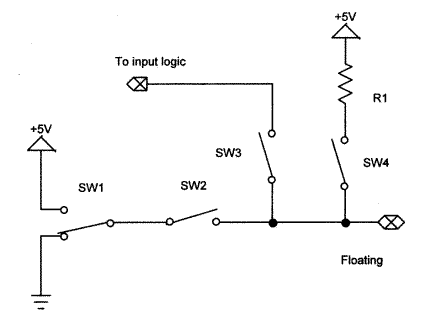
Fig. 2
In Figure 2 above illustrates the default state of a typical I/O pin when a micro-controller is first powered up. I've simplified the complex internal electronic switching to a series of on/off switches. Digital electronics after all is simply a number of solid state switches.
The initial state for most I/O pins is floating which in the electrical sense each pin on the chip is a piece of wire hanging in the air. All internal switching is open until a program or software configure the various switch combinations.
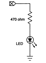
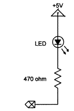
Fig. 3a Fig. 3b
Sink Versus Source
While it's possible to determine the electrical state of a micro-controller pin with say a volt-ohm meter, oscilloscope, or a logic probe, the simplest method is to use an LED or light-emitting diode. An LED like all diodes conducts current in only one direction. The arrow in the diode symbol points towards the cathode which must be connected to negative side of the circuit, and away from the anode which goes to the positive side of the circuit.
The LEDs in Fig. 3a and 3b illustrate the concept of source and sink respectively. In 3a the LED cathode is connected directly to ground while the anode through a 470 ohm resistor must be connected to some source of voltage through either an on/off mechanical switch or transistor switch within an I/O pin.
In figure 3b the LED anode is already connected to a + voltage source so to complete the electrical circuit we must sink the current to ground to light the LED again either through a mechanical switch or a transistor switch within an I/O pin.
The I/O pins on both the Atmega168-Arduino and PICAXE can sink/source a maximum current of 20 mA or 0.02 Amps each. That doesn't mean one can have 16 I/O pins operating at 20 mA each all at once.
The operating voltage of the LED varies from 1.6 volts and around 3.5 volts depending on type and amount of current. So in all cases we require a current limiting resistor when connected to 5 volts. In general I use 220 and 470 ohms; others use 330 ohms. Anything between 5-10 mA of current is plenty. For more technical information on LEDs see the following:
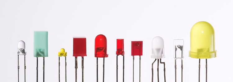
Picture of various LEDs
Basic LED Construction
How LEDs Operate
infrared 1.6 V
Red 1.8 V to 2.1 V
Orange 2.2 V
Yellow 2.4 V
Green 2.6 V
Blue 3.0 V to 3.5 V
White 3.0 V to 3.5 V
UV 3.5 V
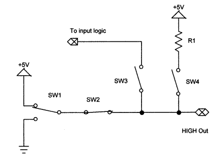
Fig. 4
Fig. 4 illustrates what happens when an I/O pin is programmed for a "HIGH" or binary 1 output. Sw1 goes to 5-volts and Sw2 closes, 5-volts will appear at the selected pin. If the LED of figure 3a was connected to the pin it would light up. The code for the PICAXE would be:.
main:
   HIGH C.6
goto main
The Arduino differs in that the digital I/O pin must be pre-configured before I can use it. The sample code below uses digital pin 6:
void setup()   {
   pinMode(6, OUTPUT);
} // end setup

void loop()   {
   digitalWrite(6, HIGH); // could also be digitalWrite(6, 1);
}  // end loop
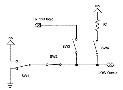
Fig. 5
Fig. 5 illustrates what happens when an I/O pin is programmed for a "LOW" or binary 0 output. Sw1 goes to ground (0-volts) and Sw2 closes, completing a connection to ground. 0 volts will appear at the selected pin. If the LED of figure 3b was connected to the pin it would light up. The code for the PICAXE would be:.
main:
   LOW C.6
goto main
The Arduino differs in that the digital I/O pin must be pre-configured before I can use it. The sample code below uses digital pin 6:
void setup()   {
   pinMode(6, OUTPUT);
} // end setup

void loop()   {
   digitalWrite(6, LOW); // could also be digitalWrite(6, 0);
}  // end loop
Note the I/O pins on a micro-controller can only drive low-power and low-voltage devices. The power levels must be boosted by other external components such as transistors and power MOSFETs. For more on that see the following:
- Basic Transistor Driver Circuits for Micro-Controllers
- Opto-Isolated Transistor Drivers for Micro-Controllers
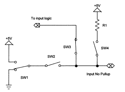
Fig. 6
So far we have looked a configuring I/O ports for output, it's time to configure an I/O pin to detect a switch. Fig. 6 above illustrates a typical I/O port configured as an input. Sw3 has closed connecting the pin electrically to the input logic while opening Sw2 disconnecting the output logic.
In the electrical sense the pin is back to floating being neither HIGH nor LOW because an input is often high impedance. Until one can determine for sure what the electrical state of the I/O pin actually is, the input at best is unreliable.
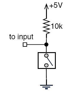
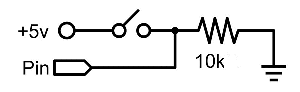
Fig. 7a Fig. 7b
In Fig. 7a we use a "pullup" resistor. This will raise the voltage to 5-volts and will read HIGH until such time as the switch is pressed and the pin will read LOW.
In Fig. 7b we use a "pulldown" resistor. This will set the voltage to 0-volts and will read LOW until such time as the switch is pressed and the pin will read HIGH.
The following PICAXE code example assumes the LED from Fig. 3a is connected B.0 (electrical pin 6) and the switch in 7b is connected to B.1 (electrical pin 7).
main:

   if pinB.1 = 1 then HIGH B.0 endif
   if pinB.1 = 0 then LOW B.0 endif

   goto main
What the above does is simply turn on the LED when the switch is pushed. If one used the switch setup in 7a the LED would stay on until the switch was pressed. Here the sample Arduino code to do the same thing using digital pin 7 for the LED and digital pin 6 for the switch:
void setup()   {

   pinMode(6, INPUT);
   pinMode(7, OUTPUT);

} // end setup

void loop()   {

   if (digitalRead(6) == 1) digitalWrite(7, HIGH);
   if (digitalRead(6) == 0) digitalWrite(7, LOW);

}  // end loop
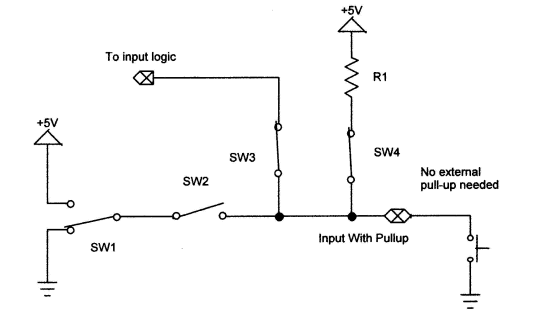
Fig. 8
Using internal Pullups
Many micro-controllers have internal pullup resistors that can be turned off/on under software control. In Fig. 8 above we have programmed our theoretical I/O port to enable both digital input and the internal pullup resistor. As shown we have eliminated any need for an external resistor and can simply connect a switch between the pin and ground.
In the PICAXE only PORTB has internal pullup resistors. Here is modification of the above program:
pullup on        ;enable pullups
pullup %00000010      ;enable pullup only on portB.1

main:

   if pinB.1 = 1 then HIGH B.0 endif
   if pinB.1 = 0 then LOW B.0 endif

   goto main
In the case of the Atmega168-Arduino all digital pins from 0 to 13 have pullups:
void setup()   {

   pinMode(6, INPUT);
   pinMode(7, OUTPUT);
   digitalWrite(6, HIGH); // enable pullup digital pin 6

} // end setup

void loop()   {

   if (digitalRead(6) == 1) digitalWrite(7, HIGH);
   if (digitalRead(6) == 0) digitalWrite(7, LOW);

}  // end loop
This concludes a brief introduction to I/O ports.
Picaxe Micro-controller Projects!
The PICAXE series of micro-controllers rank as the easiest and most cost effective way to use Microchip processors. I wanted an easier and less expensive way to introduce my students to the "PIC" micro-controller. Here I hope to get those starting out past poorly written literature and lack of simple working code examples.
- PICAXE Related videos Oct. 2016:
- Tutorial: Programming-Using PICAXE-18M2 Microcontroller
- How to setup PICAXE Pulse Width Modulation
- PICAXE TA8050P H-Bridge with Motor Control
- PICAXE TA8050P H-Bridge with Motor Speed Control
- PICAXE-18M2 Operates MOSFET H-Bridge
- PICAXE-18M2 Uses MCP23016 GPIO Expander
- Solar Panel Charge Controller Using PICAXE Microcontroller
- Exploring the PICAXE Micro-Controller
- Understanding Micro-Controller Input/Output Ports
- Using the 74HC165 Shift Register with the PICAXE Micro-Controller
- Connecting the 74HC595 Shift Register to PICAXE Micro-controller
- Using 7-Segment Displays with the PICAXE Micro-Controller
- Potentiometers and Analog-to-Digital Conversion with the PICAXE
- Pulse-Width Modulation Motor Speed Control and the PICAXE Micro-Controller
- Connecting the PICAXE to the DS1307 Real Time Clock
- Connecting the PICAXE to an External EEPROM (24LC08)
- Connecting a Servo to a PICAXE
- Connecting the TLC548 to the PICAXE
- Connecting the Ad5220 Digital Potentiometer to the PICAXE
Web site Copyright Lewis Loflin, All rights reserved.
If using this material on another site, please provide a link back to my site.