PIC16F84A H-Bridge motor controller.
Microchip PIC16F84A H-Bridge Motor Control
Also see H-Bridge Motor Control Diagram and PIC16F84A diagram.
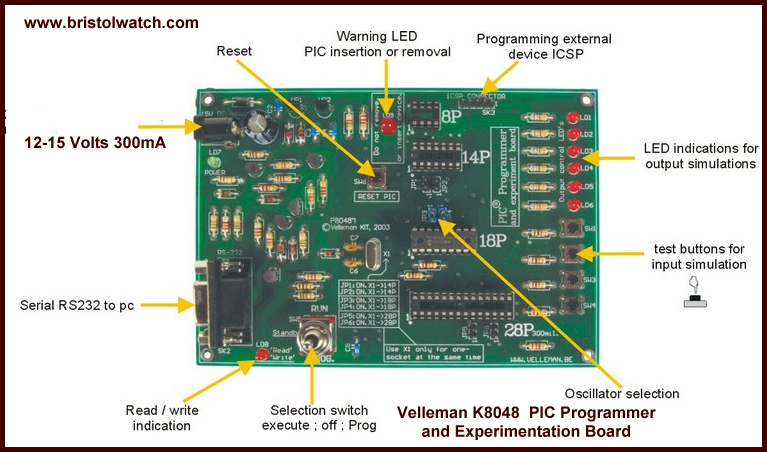
YouTube video: Using Velleman K8048 PIC Development Board
YouTube for this page: Using Velleman K8048 PIC Development Board
The PIC16F84A is a low-end RISC (reduced instruction set computer) microcontroller suitable for learning and basic control functions. It uses an external crystal up to 20 mHz. It also has 13 bi-directional I/O pins with programmable pullups on PORTB.
Note: one doesn't need an H-Bridge and not using the Velleman development board wire the above onto a proto-board and connect LEDs to PB0 and PB1.
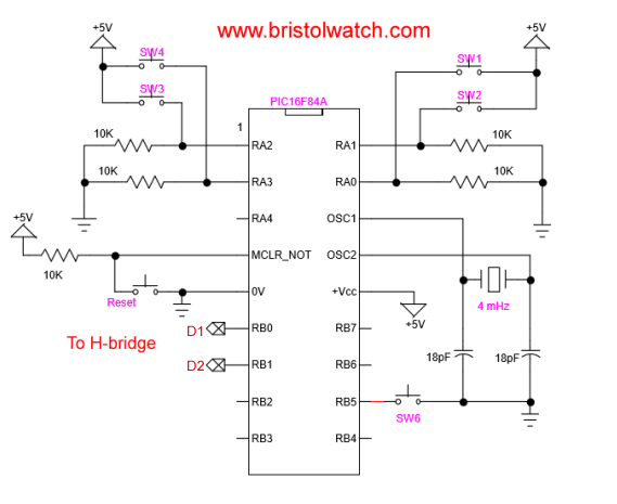
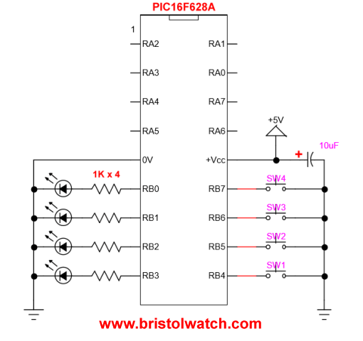
The diagram above is taken from the Velleman PIC development board used in the associated videos. Pins PA0 - PA3 are pulled low by 10K resistors while 4 switches are wired to +5V. When a switch is pressed the pin goes HIGH and indicates a switch closure. There is an external switch (SW6 off board) connected to ground. using the internal programmable pullup resistor eliminates the use of an external resistor. In this case a switch closure generates a LOW.
- Microchip PIC related:
- How to Use K150 PIC Programmer
- Microchip PIC16F628A Basic H-Bridge Motor Control
- Microchip PIC16F628A Counts BCD on 8 LEDs
- PIC16F84A Operates H-Bridge Motor Control
- PIC16F84A Operates MOSFET H-Bridge
For more information on the Velleman PIC development board see http://www.vellemanusa.com/products/view/?country=us&lang=enu&id=500373. Remember this is a kit one has to solder it together.
The complete assembly code is F84A_hb.asm. Let's walk through several sections of this code which works the same way on a PIC16F628A. I use the MPLAB 8.88 compiler and I assume one knows how to use similar software and can program a PIC chip.
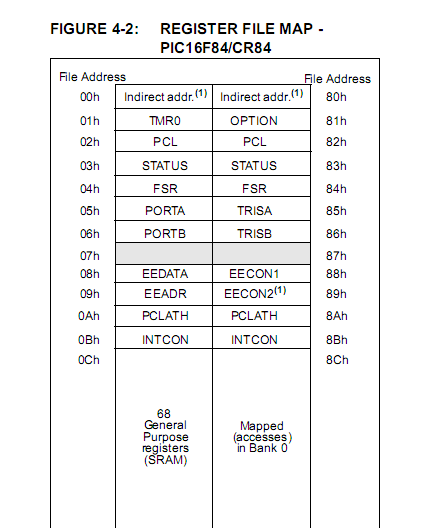
First lets look at how to activate our pullup resistors - this operates nearly the same on a number of microcontrollers. If one is new to PIC programming look over this PIC16F84A register map and the following makes more sense. Let's define a few things first:
; BANK 0
PORTA		EQU     H'0005'
PORTB		EQU     H'0006'
; BANK 1
OPTION_REG	EQU     H'0081'
TRISA		EQU     H'0085'
TRISB		EQU     H'0086'
The five 8-bit registers we will be using exist in two "banks" and the bank must be selected to read-write the register. Instead of archaic register addresses we have given them names we can better understand. Again look over the register map. We can also define our switches and LEDs on the Velleman board which refer to individual PORT and pin connections:
;INPUTS
SW1		EQU     H'00'		;SW1 is triggering RA0
SW2		EQU     H'01'		;SW2 is triggering RA1
SW3		EQU     H'02'		;SW3 is triggering RA2
SW4		EQU     H'03'		;SW4 is triggering RA3
;OUTPUTS
LD1		EQU	H'00'		;LD1 is connected to RB0
LD2		EQU	H'01'		;LD2 is connected to RB1
LD3		EQU	H'02'		;LD3 is connected to RB2
LD4		EQU	H'03'		;LD4 is connected to RB3
; I added these
SW5		EQU H'04'
SW6		EQU H'05'
Also related to this: Understanding Microcontroller IO Ports
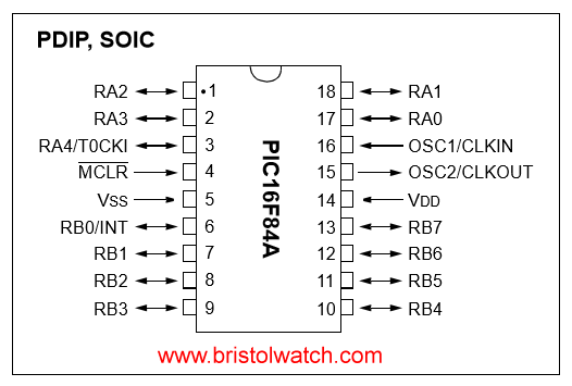
Examine the diagram at the top of the page and relate these symbols to the pin on the PIC16F84A. Note anything after ";" is a comment and ignored by the compiler. Now we are going to setup the hardware functions for the PIC16F84A:
	ORG	0 ;Setting Reset vector 000h in PIC16F84
	GOTO	SETUP	;Jump to setup procedure
	; when boot-up PIC device.

SETUP
	BSF	STATUS, RP0		  ;Jump to bank 1 of PIC16F84
	MOVLW	B'00001111'	  ;Port A - RA0 - RA3 are inputs,
	MOVWF	TRISA		  ;Set I/O configuration for PORTA
	MOVLW	B'11110000'	  ;Port B, RB4 - RB7 are inputs,
	; RB0 - RB3 are outputs.
	MOVWF	TRISB		  ;Set I/O configuration for PORTB
	BCF OPTION_REG, NOT_RBPU  ; enable PORTB pull ups

	BCF	STATUS,RP0  ;Jump back to bank 0 of PIC.
	BSF PORTB, SW6 ; pull up on PB5 switch N.O. wired to GND
	CALL OFF ; clear outputs B0-B3
When the PIC resets it goes to address 0x00 in the flash ram where it then goes to the address of "SETUP". (Don't worry the compiler knows where the address is.) RP0 is bit 5 in the STATUS register that when "set" or 1 allows to access bank 1. We load 0x0F into the W register then we move that value to TRISA the PORTA data direction register. A 1 in a selected bit makes the pin an INPUT while a 0 makes the pin an output. Thus Port A - RA0 - RA3 are inputs, we aren't using the upper 4 bits which only PA4 is available.
The same thing is done to TRISB the PORTB data direction register, but this time PB0-PB3 are outputs while PB4-PB7 are inputs. The line "BCF OPTION_REG, NOT_RBPU" sets bit 7 in the OPTION_REG register to 0 enabling the internal pullup resistors in PORTB. But we are not finished yet.
"BCF STATUS,RP0" clears (0s) bit 5 in the STATUS register taking us back to bank 0. To turn on a pullup resistor on a selected pin it must be first programmed as input, then we set the associated bit HIGH with "BSF PORTB, SW6". Finally we "CALL" a subroutine OFF that makes sure PB0-PB3 are all 0s and no output voltage - a 1 outputs 5V and a 0 switches the pin to ground.
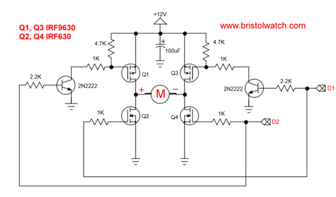
Now we have the main part of the program. The idea is to detect a switch closure and control PB0 and PB1 to control a H-bridge motor control. We should be able to run the motor forward, reverse, and stop. See the following truth table:
PB0 1; PB1 0 forward;
PB0 0; PB1 1 reverse;
PB0 0; PB1 0 stop.
See this example H-Bridge circuit that while using a PIC16F628A operates nearly identical except for the switches. Also see MOSFET H-Bridge for Arduino 2. The following is the main program and is self-explanatory:
LOOP ; Loop starts here !!!

	BTFSC	PORTA, SW1	; Test if SW1 is HIGH
	GOTO $+2 ; yes SW1 HIGH skip next line
	GOTO $+3 ; goto check SW2
	CALL OFF ; outputs off delay 500 mS
	BSF PORTB, 0 ; PB0 HIGH forward

	BTFSC	PORTA, SW2	; Test if SW2 HIGH
	GOTO $+2 ; yes SW2 HIGH skip next line
	GOTO $+3 ; no goto check SW6
	CALL OFF ; output off delay 500 mS
	BSF PORTB, 1 ; PB1 HIGH

	BTFSS	PORTB, SW6 ; Test for LOW skip next line if HIGH
	CALL OFF ; output off delay 500 mS

	GOTO  LOOP
Related: Introduction PIC12F683 Programming Circuits Tutorial
For more on this subject and a step up from the PIC16F84A see Microchip PIC16F628A H-Bridge Motor Control. Have fun.
- Microchip PIC16F84A H-Bridge Motor Control
- Microchip PIC16F628A Basic H-Bridge Motor Control
- PICAXE Operates H-Bridge Motor Controller
- PICAXE Micorcontroller Controls Motor Speed - Direction
- PICAXE Projects
- Arduino Port Registers Revisited
- Digispark ATtiny85 with MCP23016 GPIO Expander
- Safely Build Program a H-Bridge
- Build H-Bridge Motor Control Without Fireworks
- MOSFET H-Bridge for Arduino 2
- Microchip PIC related videos:
- How to Use K150 PIC Programmer
- Microchip PIC16F628A Basic H-Bridge Motor Control
- Microchip PIC16F628A Counts BCD on 8 LEDs
- PIC16F84A Operates H-Bridge Motor Control
- PIC16F84A Operates MOSFET H-Bridge
- Using Velleman K8048 PIC Development Board
- Microchip PIC16F84A H-Bridge Motor Control
- Microchip PIC16F628A Basic H-Bridge Motor Control
- PICAXE Operates H-Bridge Motor Controller
- PICAXE Micorcontroller Controls Motor Speed - Direction
- PICAXE Projects
- Arduino Port Registers Revisited
- Digispark ATtiny85 with MCP23016 GPIO Expander
- Safely Build Program a H-Bridge
- Build H-Bridge Motor Control Without Fireworks
- MOSFET H-Bridge for Arduino 2
- Web Master
- Gen. Electronics
- YouTube Channel
- Arduino Projects
- Raspberry Pi & Linux
- PIC18F2550 in C
- PIC16F628A Assembly
- PICAXE Projects
Web site Copyright Lewis Loflin, All rights reserved.
If using this material on another site, please provide a link back to my site.