
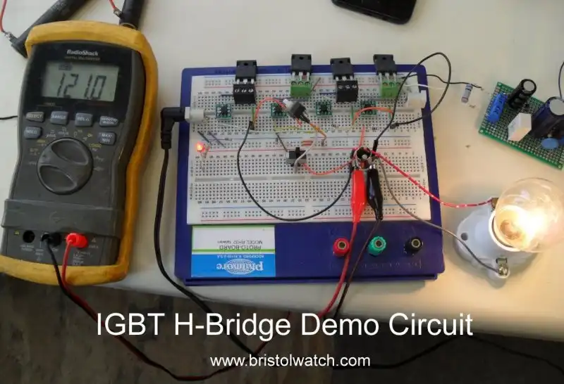
Fig. 1
Click for larger image.
IGBT Based High Voltage H-Bridge DC Motor Control
by Lewis Loflin
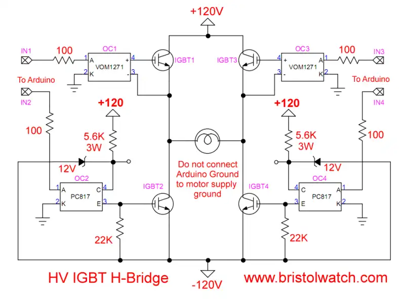
Date: August 2021. Fig. 1 is my 120V H-Bridge test circuit.
The goal here is to review transistors and the operation of H-bridge motor control circuits.
This is designed to be operated by an Arduino or similar microcontroller. I am dealing with high voltage here so read my warning page.
- Load Lamp Safely Allows Safer Electronic Testing
- Build Autotransformer-Variac AC and DC Power Supply
- Warning About Electrical Shock and How to Prevent It
Also use a current limited power supply for testing.
Use this at your own risk. For information purposes only.
This should be developed at a lower voltage (18V), current limited to 1 amp, then debugged before moving to a higher voltage.
See Constant Current Source Theory Testing.
One also needs to review IGBTs and photovoltaic opto-couplers even though I will go over them here.
I also include my MOSFET based H-Bridge for a review.
- H-Bridge Motor Control with Power MOSFETs
- VOM1271 Photovoltaic MOSFET Driver Circuits
- Insulated Gate Bipolar Transistor IGBT Circuits Tutorial
- From Basic Digital Circuits to H-Bridge Motor Controls
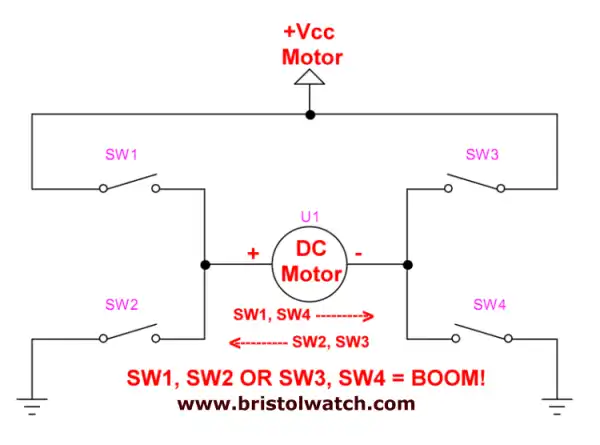
Fig. 2
What is an H-Bridge Motor Control?
An h-bridge consists of four switches arranged as in Fig. 2 with a permanent magnet DC motor connected between the switch pairs.
SW1 and SW3 will be referred to as "high-side" switches. Also known as "source" will switch the positive side of the power supply to the load.
SW2 and SW4 will be referred to as "low-side" switches. Also known a "sink" the current to common or ground.
These switches can be mechanical toggle switches, relay contacts, or various forms of transistor switches. Here I'm concerned with transistor switches.
If SW1 and SW4 are closed current flow from positive to negative terminals through the motor. The motor rotates clockwise.
Open SW1 and SW4. Never turn on SW1 and SW2 at the same time, never turn on SW3 and SW4 at the same time. The power supply will be damaged and so will the switches.
Close SW2 and SW3 current will flow from negative to positive terminals through the motor. The motor will rotate counter-clockwise.
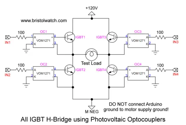
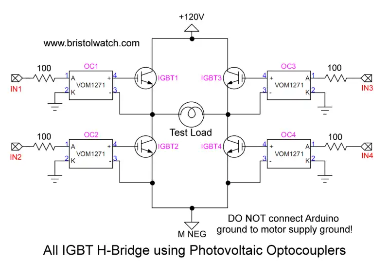
Fig. 3
Click for larger image.
All IGBT H-Bridge Circuit?
I had a visitor request to design a 120-volt DC H-bridge circuit using IGBTs or insulated gate bipolar transistors.
The working design is shown in Fig. 1, the schematic to an all IGBT using photovoltaic opto-couplers in Fig. 3.
They have the advantage MOSFET gate characteristics combined with bipolar transistor high-voltage switching.
The design solves the problem of isolating the high motor voltage from the microcontroller. When 5-volts or HIGH is input to the VOM1271 it generates 8-volts across the gate-emitter of the IGBT turning on the device.
IN1 can be turned on the same time as IN4 motor goes clockwise. IN2 and IN3 on the motor goes counter-clockwise.
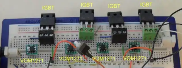
Fig. 4
Click for larger image.
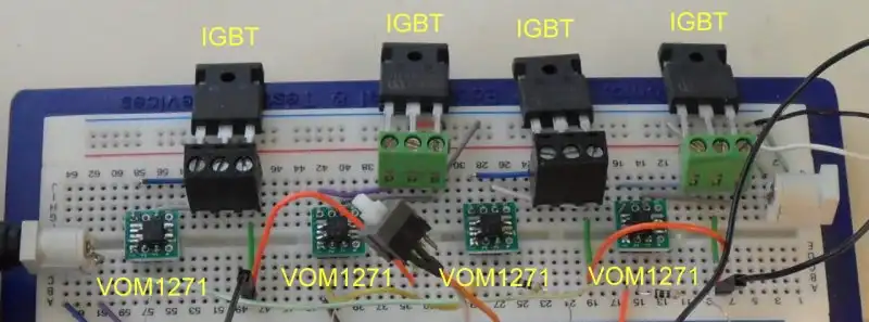
Fig. 4 is a close up view of the IGBTs and opto-couplers.
The VOM1271s are surface mount devices I had to solder onto a SOP carrier board. I got 25 for $5.
This works great as but has one flaw: motor speed control though pulse-width-modulation.
My test show the opto-couplers have slow response time on turn off. Yes they have internal gate shutoff but it is slow.
The other problem is the "high-side" IGBTs must use the photovoltaic opto-couplers. MOSFETs and bipolar transistors n-channel/p-channel or NPN/PNP compliments, the IGBT really doesn't.
I hunted around for them and found a few that are very rare and expensive. There is a way around this if one needs to use pwm.
Note Arduino PWM works OK as is with 4 VOM1271s.
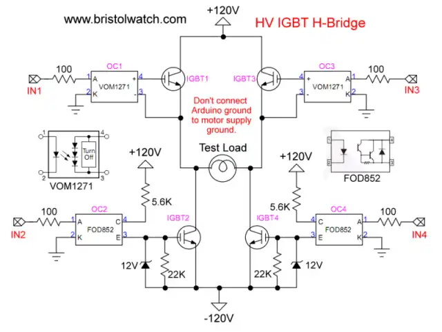
Fig. 5
Click for larger image.
Fig. 5 illustrates using high-voltage FOD852 type opto-coupler with the "low side" IGBTs. Switching on the FOD852 through a 5.6K 3-watt resistor allows the Zener 12-volt diode to turn on the IGBT.
To pulse width modulate turn on the corresponding "high-side" IGBT and use PWM on the "low-side" IGBT.
The FOD852 internal Darlington photo transistor is rated at 300-volts.
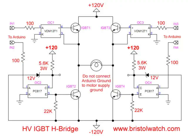
Fig. 6
Click for larger image.
If one doesn't have a high-voltage opto-coupler use the schematic in Fig.6.
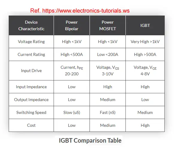
Fig. 7 IGBT bipolar transistor comparison table.
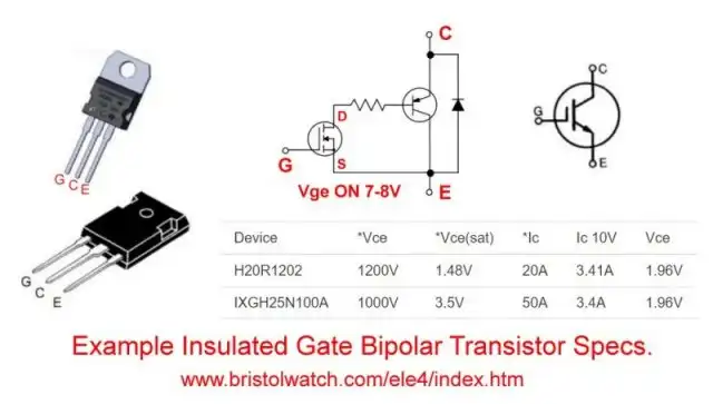
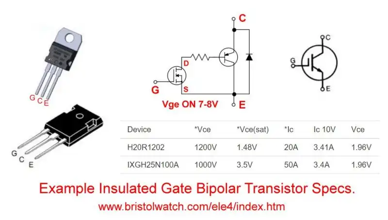
Fig. 8 Package connections and internal circuit for IGBTs.
Click for larger image.
Some Arduino Code
Connect IN1 to IN4 then connect to Arduino digital pin 5.
Connect IN2 to IN3 then connect to Arduino digital pin 6.
Download the Arduino code: igbt.txt
![]()
- Quick navigation of this website:
- You Tube Channel
- Basic Electronics Learning and Projects
- Homepage Lewis Loflin
- Follow on X
- Skeptic Site
- Religion 1
- Religion 2
- Coils for Highly Selective Crystal Radio
- Neon (NE-2) Circuits You Can Build
- Understanding Xenon Flashtubes and Circuits
- Hall Effect Magnetic Switches and Sensors
- Transistor-Zener Diode Regulator Circuits
- Build an Adjustable 0-34 volt power supply with the LM317
- Simple 2 Transistor LED Flasher Circuit
- LM2575 Simple Switching Voltage Regulators
- LM317 Constant Current Source for Lighting LEDs
- IGBT Based High Voltage H-Bridge DC Motor Control
- Arduino Controlled IR2110 Based H-Bridge HV Motor Control
- Understanding Unijunction Transistors Theory Operation
- Arduino Measures Current from Constant Current Source
- Constant Current Source Theory Testing
- Review Ohm's Law for Trouble-Shooting CCS Circuits
- Arduino Power Magnetic Driver Board for Stepper Motors
- Arduino Controlled Power Constant Current Source
- Theory and Operation of Capacitors
Related video to above:
- Measure Current from Constant Current Source with Arduino
- Constant Current Source Multimeter Trouble Shooting
- Ohm's Law Review for Constant Current Source
- Arduino Unipolar Stepper Motor Driver Board with Arduino Code
- Arduino Controlled Constant Current Source
- LM317 Adjustable Current Boost Power Supply
- Constant Current Circuits LM334, LM317
- Build LM317 0-34 Volt Power Supply
- LM334 Constant Current Source with Resistive Sensors
- LM317 High Power Constant Current Source Circuit
- LM317 Constant Current Source Circuits
- Test SCRs and Triacs
- Basic MOSFET Transistor Test Circuits
- High Voltage MOSFET Switching Circuits
- 3 Amp LM741 Op-Amp Constant Current Source
- Current Limiter Testing of Zener Diodes
- Current Limiter for Opto-Coupler Inputs
- LM317 CCS for Light Emitting Diodes
Web site Copyright Lewis Loflin, All rights reserved.
If using this material on another site, please provide a link back to my site.