Fig. 1
Comparing Photo Triac Photo SCR, and Photovoltaic Opto-Couplers
by Lewis Loflin
Broad introduction to opto-couplers and practical circuits. Review of opto-coupler types and uses focusing on solid state relays and power control.
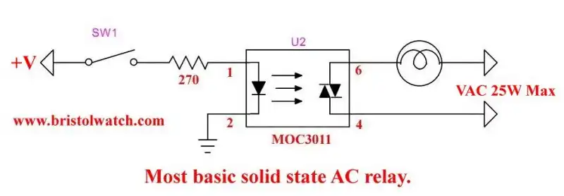
In Fig. 1 is a very basic solid state AC relay. The MOC10XX and MOC20XX can drive 25 watt loads. This is well within the current ratings of many LED light bulbs.
In the case of my YouTube video I used a 8-watt LED lamp switched on/off with an Arduino microcontroller.
The following is from the manufacturer data sheet:
Detector 300mW at 1A peak
MOC3010M/1M/2M 250V peak
MOC3020M/1M/2M/3M 400V peak
The only difference besides the peak voltage is the current through the LED photo emitters. I'll be using a number of these in power switching circuits. They are "random phase" devices.
They can be used in lamp dimmer circuits.
To quote the data sheet:
The MOC301XM and MOC302XM series are optically isolated triac driver devices. These devices contain a GaAs infrared emitting diode and a light activated silicon bilateral switch, which functions like a triac. They are designed for interfacing between electronic controls and power triacs to control resistive and inductive loads for 115 VAC operations.
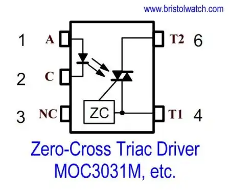
Fig. 2
In Fig. 2 we have the internal diagram of the MOC30XX and MOC40XX Triac output opto-coupler with internal "zero-cross" circuits. I won't be using these due to the inability to phase modulate the device.
The data sheet notes:
The MOC303XM and MOC304XM devices consist of a AlGaAs infrared emitting diode optically coupled to a monolithic silicon detector performing the function of a zero voltage crossing bilateral triac driver.
They are designed for use with a triac in the interface of logic systems to equipment powered from 115 VAC lines, such as teletypewriters, CRTs, solid-state relays, industrial controls, printers, motors, solenoids and consumer appliances, etc.
These can drive low power AC devices.
Detector 150mW 1A peak current
MOC3031M/2M/3M 250V peak
MOC3041M/2M/3M 400V peak
The data sheet is vague on current values for the output circuit. The dissipation is half the MOC10XX series.
These can't be used in lamp dimmer circuits as the turn on point is fixed by the zero-crossing circuit. This is good for simply switching on higher power Triacs or dual SCR outputs.
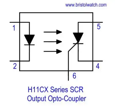
Fig. 3
The H11C series consists of a gallium-arsenide infrared emitting diode optically coupled with a light activated silicon controlled rectifier in a 6-pin dual-in-line package. They come in voltage ratings of 200 and 400 volts.
The data sheet call this "symmetrical transistor coupler".
25 W logic indicator lamp driver
Detector 400mW RMS on state current 300mA
200 V symmetrical transistor coupler (H11C1, H11C2, H11C3)
400 V symmetrical transistor coupler (H11C4, H11C5, H11C6)
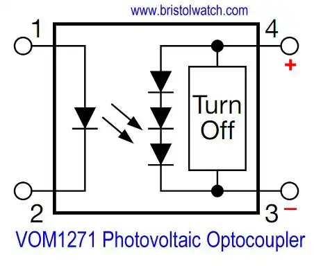
Fig. 4
The VOM1271 photovoltaic MOSFET driver is shown in Fig. 4. This consists of a series of photo diodes producing about 8 volts to drive MOSFET based devices. To quote,
The VOM1271 is a stand-alone optically isolated MOSFET driver. Unlike conventional MOSFET drivers, which require an external power supply to provide VCC and or VDD rails to the driver itself, the VOM1271 obtains all the required current to drive its internal circuitry from the LED current on the low voltage primary side of the isolation barrier.
This saves the designer the space and cost associated with providing one or more external power supplies. The VOM1271 also integrates a turn-off circuit internal to the component itself, thus doing away with the need for additional components in order to increase the overall switching speed by decreasing the turn-off time.
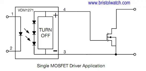
Fig. 5
Fig. 5 VOM1271 photovoltaic MOSFET driver with MOSFET transistor.
- Reference:
- H11CX Photo SCR Optocouplers
- MOC10XX and MOC20XX Triac Output Optocouplers
- MOC30XX and MOC40XX Zero-Cross Opto-Couplers
- Exploring Solid State Relays and Control Circuits
- Comparing Photo Triac, Photo SCR Opto-Couplers
- Light Activated SCR Based Optocouplers Circuit Examples
- Silicon Controlled Rectifier Review and Circuits
- Silicon Controlled Rectifiers Connected as Power Triacs
- Insulated Gate Bipolar Transistor IGBT Circuits
- Current Limiter Circuits for Opto-Coupler LEDs
- VOM1271 Photovoltaic MOSFET Driver Circuits
- Current Limiter Allows Safe Testing of Zener Diodes, LEDs
- 3 Amp LM741 Op-Amp Constant Current Source
- Bidirectional Solid State Relay Circuits
- Simple Solid State Relay for Low Power LED 120V Lamps
- Build High Power MOSFET Directional Switch Relay
- Optical Isolation of H-Bridge Motor Controls
- All NPN Transistor H-Bridge Motor Control
- Basic Transistor Driver Circuits for Micro-Controllers
- ULN2003A Darlington Transistor Array with Circuit Examples
- Tutorial Using TIP120 and TIP125 Power Darlington Transistors
- Driving 2N3055-MJ2955 Power Transistors with Darlington Transistors
- Understanding Bipolar Transistor Switches
- N-Channel Power MOSFET Switching Tutorial
- P-Channel Power MOSFET Switch Tutorial
- Build a Transistor H-Bridge Motor Control
- H-Bridge Motor Control with Power MOSFETS
- More Power MOSFET H-Bridge Circuit Examples
- Build a High Power Transistor H-Bridge Motor Control
- H-Bridge Motor Control with Power MOSFETS Updated
- Opto-Isolated Transistor Drivers for Micro-Controllers
- Comparator Theory Circuits Tutorial
- Constant Current Circuits with the LM334
- LM334 CCS Circuits with Thermistors, Photocells
- LM317 Constant Current Source Circuits
- TA8050P H-Bridge Motor Control
- All NPN Transistor H-Bridge Motor Control
- Basic Triacs and SCRs
- Comparator Hysteresis and Schmitt Triggers
- Comparator Theory Circuits Tutorial
- Photodiode Circuits Operation and Uses
- Optocoupler MOSFET DC Relays Using Photovoltaic drivers
- Connecting Crydom MOSFET Solid State Relays
- Photodiode Op-Amp Circuits Tutorial
- Optocoupler Input Circuits for PLC
- H11L1, 6N137A, FED8183, TLP2662 Digital Output Optocouplers
- Optical Isolation of H-Bridge Motor Controls
- All NPN Transistor H-Bridge Motor Control
© Copyright 2019 Lewis Loflin E-Mail