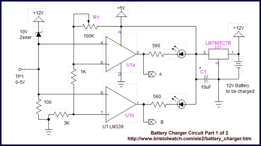
Fig. 1 click picture for full size.
Non-Micro-controller Solar Panel Battery Charge Controller
The goal of this project is to build a 12-volt battery charger to use with my solar panels without the use of a micro-controller such as Arduino or PIC. We will make use of comparators circuit with basic digital gates.
Also see Comparator Theory Circuits Tutorial
The circuit evolves around a LM339 quad comparator with open collector output. Referring to Fig. 1 where the comparator outputs a LOW will switch on the associated LED. The output of the LM339 or one can substitute 2 LM311s is open collector. When the voltage on the "-" input exceeds the voltage on the "+" input the internal transistor is switched to ground and the LED is turned on.
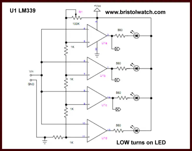
Here I've used only two of the four available comparators - feel welcome to add the extra LEDs if needed. See 4 LED voltage meter.
While the main circuit is 12-volts we must have a stable reference voltage for the comparators. The trip points are determined by the resistors and the 100K pot R1. When properly adjusted LED on B will turn on at about 12.6-volts and the LED on B at about 13.6-volts.
These two outputs through the CMOS digital logic will determine when the charging voltage is turned on if the battery voltage is too low and turn off the charging voltage when charged.
We want the charge voltage on at 12.5-volts, charge the battery to 13.5-volts then turn off the charge voltage and stay off until the battery voltage drops to about 12.5-volts. The 10-volt Zener diode and the 100-ohm resistor is used to drop 10-volts so the input to the comparators is between 0-5 volts.
See LM339 spec sheet.
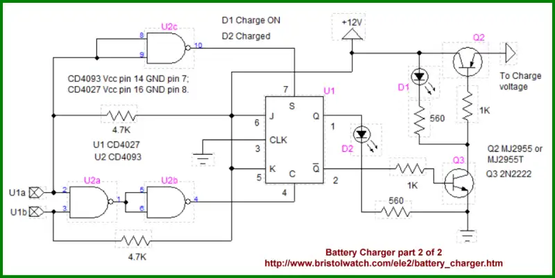
Fig. 2 click picture for full size.
The outputs A and B from Fig. 1 connect to the associated inputs on a CD4093 quad NAND gate as shown in Fig. 2. When the LEDs are both OFF indicating LOW battery voltage the two 4.7K resistors pull the inputs of U2a HIGH and through U2b will clear the CD4027 JK flip-flop producing a HIGH on pin 2.
Through a 1K resistor we switch on Q3 which then switches on Q2 supplying voltage from a solar panel or other DC source to charge the battery. When the battery is charged to 13.6-volts or so U2c input will be LOW, output a HIGH setting the JK flip-flop where pin 2 is LOW turning OFF Q3 and Q2.
The power supply-ground pins on the CD4027 and CD4093 are not shown and Vcc must be 12-volts. They are as follows:
CD4093 Vcc pin 14 GND pin 7;
CD4027 Vcc pin 16 GND pin 8.
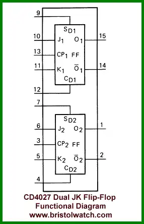
Also see CD4027 functional diagram.
- Quick navigation of this website:
- Basic Electronics Learning and Projects
- Basic Solid State Component Projects
- Arduino Microcontroller Projects
- Raspberry Pi Electronics, Programming
- Comparator Circuits:
- Comparator Theory Circuits Tutorial
- Comparator Hysteresis and Schmitt Triggers
- Voltage Comparator Information And Circuits
- Looking at Window Comparator Circuits
- Analog Battery Charger Uses Comparators
- Battery Charger related:
- Solar Panel Charge Controller Using Arduino
- Solar Panel Charge Controller Using PICAXE
- Solar Panel Battery Charge Controller Using Arduino
- Solar Panel Battery Charge Controller Switching Circuit
Arduino
- Arduino
- Arduino PWM to Analog Conversion
- Arduino Analog Digital Conversion Voltmeter
- Better Arduino Rotary Encoder Sensor
- Simple 3-Wire MAX6675 Thermocouple ADC Arduino Interface
Other Circuits
- Hall Effect Magnetic Switches and Sensors
- Transistor-Zener Diode Regulator Circuits
- Build an Adjustable 0-34 volt power supply with the LM317
- Coils for Highly Selective Crystal Radio
- Neon (NE-2) Circuits You Can Build
- Understanding Xenon Flashtubes and Circuits
- LM2575 Simple Switching Voltage Regulators
- Simple 2 Transistor LED Flasher Circuit
- Generating High Voltage with an Inductor
Web site Copyright Lewis Loflin, All rights reserved.
If using this material on another site, please provide a link back to my site.