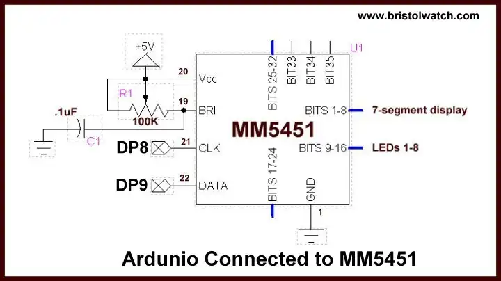
Fig. 1
Program Interface Arduino MM5451 LED Display Driver
The subject here is connecting the Arduino to a MM5451 LED display driver. This is written in C to demonstrate bitwise programming and shift register operation.
Using only two input pins (clock and data) for serial date input produces 35 open drain outputs. The 35 outputs are 15mA sink.
Internal current generator eliminates need for external resistors and has continuous brightness control. Wide supply voltage up to 13.2V - inputs TTL level.
See:
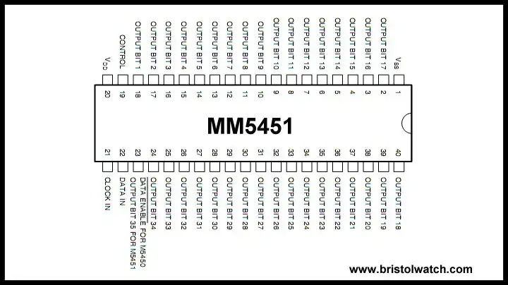
MM5452 pin connections.
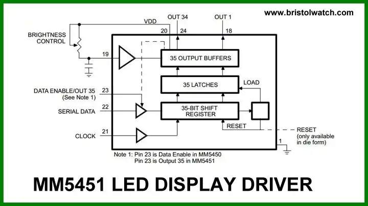
MM5451 block diagram.
A single pin controls the LED display brightness by setting a reference current through a variable resistor connected to VDD or to a separate supply of 13.2V maximum.
The M5451 are specially designed to operate 4 or 5-digit alphanumeric displays with minimal interface with the display and the data source. Serial data transfer from the data source to the display driver is accomplished with 2 signals, serial data and clock.
Using a format of a
leading "1" followed by the 35 data bits allows data transfer without an additional load signal. The 35 data bits are latched after the 36th bit is complete, thus providing non-multiplexed, direct drive to the display.
Note: these are open drain outputs that switch to ground when the associated bit is HIGH. Outputs change only if the serial data bits differ from the previous time.
Display brightness is determined by control of the output current LED displays. A 0.001uF capacitor should be connected to brightness control, pin 19, to prevent possible oscillations.
Connecting to Arduino
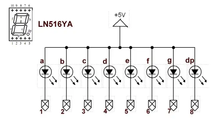
Fig. 1 shows the two connections to Arduino. MM5451 pins 11-18 (Bits 0-7) are connected to a LN516YA common-anode display (schematic). Bit 1 is segment a. 8-LEDs are connected to pins 3-10 - all anodes go to Vcc of 5V. Note no current limiting resistors are required.
Segment code for the LN516YA is stored in array segCode where segCode[0] displays 0, etc. There are two serial shift routines ssrWriteMSB(value) and ssrWriteLSB(value) used based on the viewing angle of the LEDs. Note routines zeroWrite() and pulseCLK().
Within the "for" loop the sequence starts by placing a HIGH (1) in the data pin then sending a clock pulse. Next myCount using a modulus function with 10 is shifted out to the MM5551 then the binary count itself is shift out.
That is only 16-bits but we must have 36 clock cycles before the data will be latched to the 35 output pins. (Bit 36 is not output!) Routine zeroWrite(21) takes care the remaining bits need (I set this to 0s) to enable the internal latch function.
The value of 21 used here is based on 36 - 16 bits used which is 20: the Python for loop counts from zero so it's 20 + 1. This value changes based on bits shifted in.
As the program runs we get a binary count on the LEDs and 0-9 on the display.
Download Arduino code mm5451.txt. Copy and paste to Arduino compiler.
- Quick navigation of this website:
- Basic Electronics Learning and Projects
- Basic Solid State Component Projects
- Arduino Microcontroller Projects
- Raspberry Pi Electronics, Programming
- Electronics hacks:
- Connecting PCF8574P GPIO Expander to Raspberry Pi
- Programming PCF8574P 8-bit I-O Expander with Arduino
- Raspberry Pi MM5451 LED Display Driver
- Raspberry RTC with MAX7219 Display Driver
- Raspberry Pi 8-Digit LED MAX7219 Display Driver
- Raspberry Pi 74HC595 Serial Shift Register
- Interface I2C LCD to Raspberry Pi in C
- ADS1115 4-Channel ADC Uses I2C with Raspberry Pi
- MCP4725 12-Bit DAC Interface to Raspberry Pi
- WiringPi and Pulse-Width-Modulation with Raspberry Pi
- Raspberry Pi and MAX6675 thermal-couple sensor
- WiringPi Blink an LED Demo
- Simple GPIO Reference Box
- Raspberry Pi with PCF8591 ADC in C
- Raspberry Pi PCF8591 AD-DA Sensor Python Interface
Web site Copyright Lewis Loflin, All rights reserved.
If using this material on another site, please provide a link back to my site.