Fig. 1
Testing the TA8050P H-Bridge Motor Control
TA8050P H-Bridge Motor Control YouTube Video
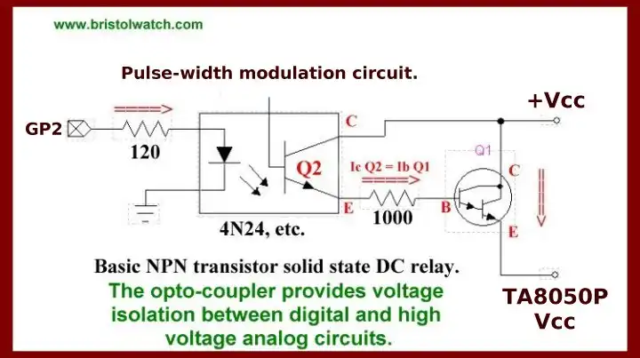
Here we connect a TA8050P h-bridge control integrated circuit to a PIC12F683 micro-controller. The unit is rated at 6-16 volts at 1.5 amps. In addition we will control motor speed by pulse-width-modulation of the power supply positive terminal. In Fig. 1 we have the actual test setup as used in the video.
See Using Arduino with the TA8050 Motor Controller
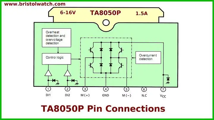
The TA8050P is a 1.5 A motor driver that directly drives a bidirectional DC motor.
Inputs DI1 and DI2 are combined to select one of forward, reverse, stop, and brake modes. Since the inputs are TTL-compatible, this IC can be controlled directly from a CPU or other control system.
The IC also has various protective functions.
Fig. 1 is the pin connections for the TA8050P.
Features:
Bidirectional DC motor driver
Current capacity : 1.5 A
Four modes : Forward, Reverse, Stop, and Brake
Recommended operating supply voltage range: VCC = 6 V to 16 V
Detection functions : Overheat Detection, Over current Detection, and Over voltage Detection
Built-in diodes for absorbing counter-electromotive force.

Fig. 3
Fig 3 shows the direct connection to a 5-volt micro-controller in this case a PIC12F683.

Fig. 4 function table.
Note: Brake mode comes into effect when both M (+) and M (-) go Low; Stop mode comes into effect when both M (+) and M (-) turn OFF.

Fig. 5
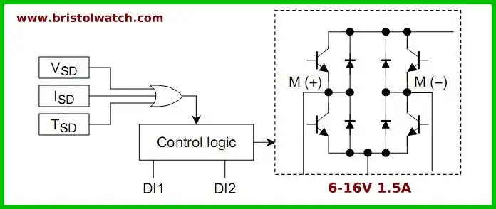
The TA8050P has functions for detecting over voltage (VSD), over current (ISD), and overheating (TSD). These functions temporarily protect the IC (and the motor load in some cases) from deterioration or destruction due to power-related over stress.

Fig. 6
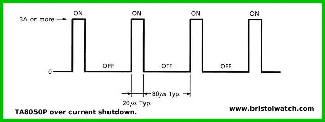
When the output current (pin 3 or 5, I sink or I source) is up to the ISD detection current, the output is controlled by the input signals. When it exceeds the detection current, the output assumes a switching waveform as shown in Figure 6.

Fig. 7
- Quick navigation of this website:
- Basic Electronics Learning and Projects
- Basic Solid State Component Projects
- Arduino Microcontroller Projects
- Raspberry Pi Electronics, Programming
- Digital Circuits:
- Simple Schmitt Trigger SN74HC14 Square Wave Generator
- Introduction to RC Differentiator Circuits and Uses
- SN74HC14 Square Wave Generator uses SN7476 JK Flip-Flop
- SN74C14 Three Output Pulse Generator Circuit
- Astable CD4047 Geiger Counter Power Supply
- CD4047 Monostable Multivibrator Circuit
- Basic TTL Tri-State Buffer Circuit Examples
- Tutorial NOR Gate SR Latch Circuits
- Tutorial NAND Gate SR Latch Circuit
- Tutorial OR-NOR Circuits Including Monostable Multivibrator
- Brief Tutorial of XOR and XNOR Logic Gates
- LM555-NE555 One-Shot Multivibrator AC Power Control
- YouTube:
- Three Output Digital Pulse Generator
- Digital Circuits:
- Two Transistor LED Flasher Circuit
- Astable CD4047 Geiger Counter Power Supply
- CD4047 Monostable Multivibrator Circuit
- Basic TTL Tri-State Buffer Circuit Examples
- Tutorial NOR Gate SR Latch Circuits
- Tutorial NAND Gate SR Latch Circuit
- Coils for Highly Selective Crystal Radio
- Neon (NE-2) Circuits You Can Build
- Understanding Xenon Flashtubes and Circuits
Web site Copyright Lewis Loflin, All rights reserved.
If using this material on another site, please provide a link back to my site.