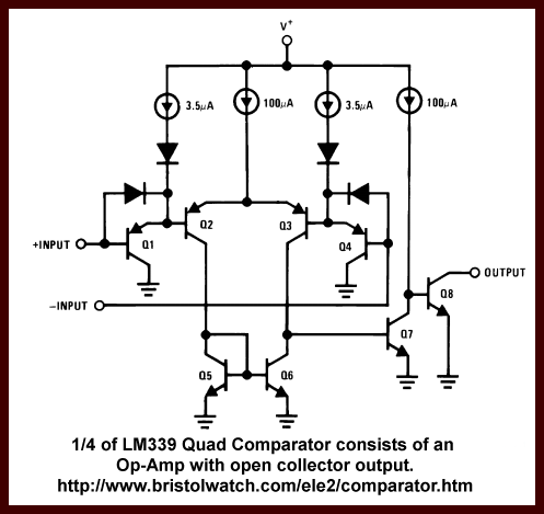
Fig. 1 Internal connections of 1/4
LM339 quad comparator.
Click picture for full size.
Voltage Comparator Circuits
by Lewis Loflin
This page provides basic information about voltage comparator
integrated circuits and is to act as reference material for other circuits. The
circuits shown are based on the LM339 Quad Voltage Comparator or the LM393
Dual Voltage Comparator.
These devices are functionally identical. The
LM311 Voltage Comparator can be used for these applications as well and also has
a number of unique features.
Here I'll concentrate on examples not presented on my Comparator Circuits Examples Tutorial. I'd like to thank Rob Paisley for his hard work and inspiration.
YouTube Video: Comparator Circuits Introduction
See my page Looking at Window Comparator Circuits
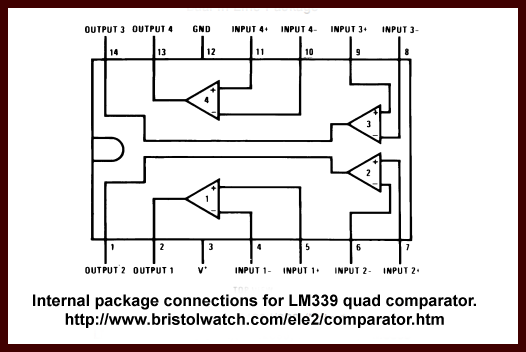
Fig. 1 shows the internal equivalent circuit of a single comparator in the LM339 quad comparator. (See internal package connections for LM339.) It consists of an operational amplifier with an open collector output transistor.
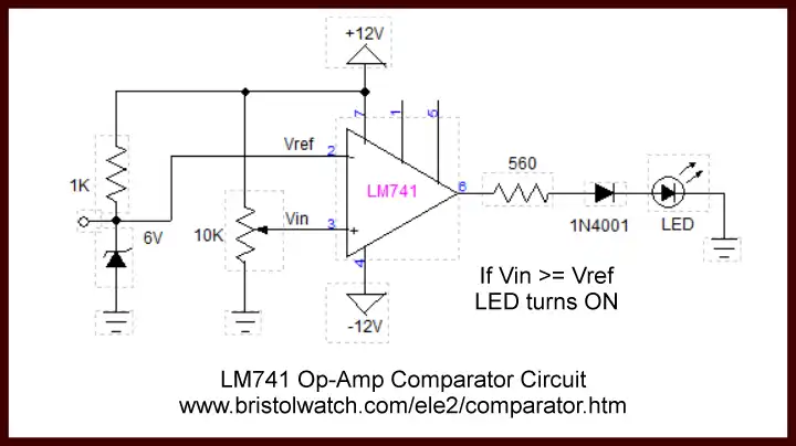
Fig. 2 LM741 based comparator
uses bipolar power supply- click picture for full size.
Fig. 2 shows the use of a LM741 op-amp comparator circuit. This requires a bipolar power supply and creates a number of problems. We can use a LM358 single supply op-amp. Fortunately the LM339, LM393, and LM311 are all single supply comparators with open collector outputs.
They all work the same: when the voltage on the Reference input is greater than the voltage input the output is switched ON or OFF.
Fig. 3 Non-inverting comparator.
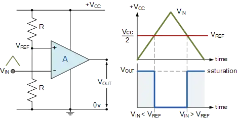
Fig. 4 Inverting comparator.
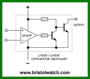
Fig. 5 LM339 functional equivalent.
The LM311 differ from the LM339 and LM393 in the output transistor emitter has to be connected to ground externally.
In the case of the LM358 or LM741 it outputs a voltage while the open collector turns on creating a path to ground - an electronic ON-OFF switch.
To repeat once more on the rule for comparator inputs with open collector outputs:
Current WILL flow through the open collector when the voltage at the MINUS input is higher than the voltage at the PLUS input.
Current WILL NOT flow through the open collector when the voltage at the MINUS input is lower than the voltage at the PLUS input.
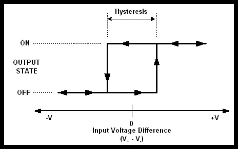
Fig. 6
Hysteresis
Hysteresis is defined as:
For slow time changing input signal, an output oscillation can appear while the input signal remains close to the reference voltage. Also low amplitude signal on high impedance can cause oscillations due to noise background.
Such unwelcome behavior can be solved by hysteresis. The principle of hysteresis consists of two different input threshold voltages depending on actual output state.
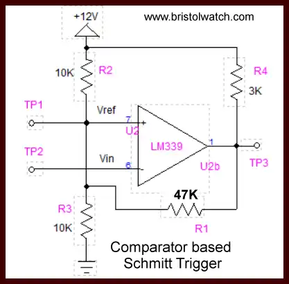
Fig. 7 Comparator based Schmitt Trigger.
In Fig. 7 we have a comparator based Schmitt trigger which are used to assure clean switching with noisy or erratic signals. When the input voltage on TP2 is less than TP1 the comparator is in the OFF condition. TP3 is pulled up to nearly 12-volts by R4 a 3K resistor.
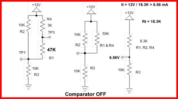
Fig. 8
Fig. 8 illustrates how when the comparator is OFF as R4 and R1 form a series 30K which is in parallel with R2 shifting TP1 (Vref) to 6.56-volts.
Without R1 Vref would be 6-volts.
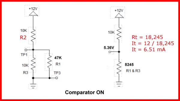
Fig. 9
When the comparator is ON TP3 is switched to ground through the internal open collector transistor where 47K resistor R1 is now in parallel with 10K resistor R3 forming a total resistance of 8245 ohms. This drops Vref on TP1 to 5.36-volts.
It takes 6.56-volts on Vin to turn ON the comparator but the voltage will have to drop to 5.36-volts to turn off. This produces a switching gap or hysteresis value of ~1.2-volts helping to assure stable operation.
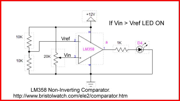
Fig. 9 LM358 op-amp inverting comparator.
Click picture for full size.
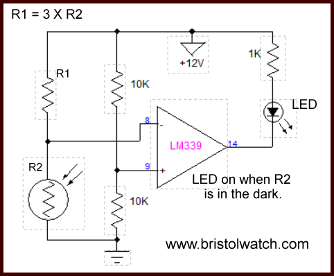
Fig. 10 Photocell comparator circuit turns on in dark.
- Quick navigation of this website:
- Basic Electronics Learning and Projects
- Basic Solid State Component Projects
- Arduino Microcontroller Projects
- Raspberry Pi Electronics, Programming
A Hall sensor in its most basic form is an analog integrated circuit. It consists of a Hall plate that outputs a "transverse" voltage based on the intensity of a magnetic field - polarity is dependant on magnetic polarity.
It also consists of a high gain differential amplifier because the generated voltage is small. The output voltage is analog usually centered around half the power supply voltage.
The addition of a Schmitt trigger with a properly set hysteresis will create a Hall switch or Hall latch. They often have an open collector output transistor.
The Schmitt triggers used here are based on an analog comparator. These can be built from operational amplifiers (op-amps) like the LM358 or LM741.
Or one can use the LM311 or LM339 quad comparator. The have open collector outputs unlike the LM311/LM741.
Often considered "digital" at this point we have in reality a one-bit analog-to-digital converter.
- Comparator Theory Circuits Tutorial
- Comparator Hysteresis and Schmitt Triggers
- Voltage Comparator Information And Circuits
- Looking at Window Comparator Circuits
- ULN2003A Darlington Transistor Array with Circuit Examples
- Tutorial Using TIP120 and TIP125 Power Darlington Transistors
- Driving 2N3055-MJ2955 Darlington Transistors
- Understanding Bipolar Transistor Switches
- N-Channel Power MOSFET Switching Tutorial
- P-Channel Power MOSFET Switch Tutorial
- H-Bridge Motor Control with Power MOSFETs
- Arduino Controlled IR2110 Based H-Bridge HV Motor Control
- IGBT Based High Voltage H-Bridge DC Motor Control
- More Power MOSFET H-Bridge Circuit Examples
- Build a High Power Transistor H-Bridge Motor Control
- Related:
- N-Channel Power MOSFET Switching Tutorial
- P-Channel Power MOSFET Switch Tutorial
- Test Power MOSFET Transistors, Observations
- Issues on Connecting MOSFETs in Parallel
- Basic MOSFET Transistor Test Circuits
- High Voltage MOSFET Switching Circuits
- Why Your MOSFET Transistors Get Hot YouTube
- Issues on Connecting MOSFETs in Parallel YouTube
- Simple Circuits for Testing MOSFET Transistors YouTube
See the following spec sheets:
- Basic Triacs and SCRs
- Constant Current Circuits with the LM334
- LM334 CCS Circuits with Thermistors, Photocells
- LM317 Constant Current Source Circuits
- TA8050P H-Bridge Motor Control
- All NPN Transistor H-Bridge Motor Control
- Basic Triacs and SCRs
- Comparator Theory Circuits Tutorial
Web site Copyright Lewis Loflin, All rights reserved.
If using this material on another site, please provide a link back to my site.