The most basic solid state relay.
Solid State AC Relays Using Triacs
by Lewis Loflin
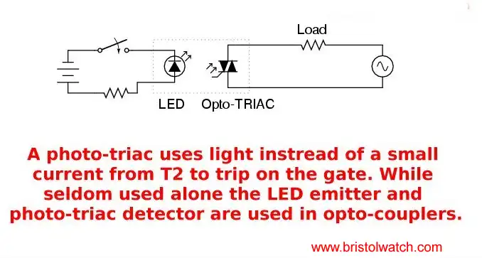
The most basic solid state relay (SSR) is shown above being a light source and a triac with a photosensitive gate. For more information on how triacs and SCRs operate see Basic Triac and SCR Projects and Circuits. A solid state relay (SSR) consists of four main parts:
- An opto-isolator or opto-coupler to isolate the low voltage DC control, often from a microcomputer, from the high voltage AC. The input opto-coupler is often a light emitting diodes while the output is often a photo transistor or photo Diac for switching on a triac.
- The SSR often has an internal zero-crossing detector circuit to switch on the triac during the time the sin wave is a little past zero or 180 degrees. This helps prevent damage the load and needless power surges.
- A triac acting as an AC switch. If the SSR is for DC the output is a power transistor.
- A snubber circuit(s) to prevent false firing of the triac from noise spikes generated with magnetic loads.

A more practical SSR.
Also see Using Opto-Couplers An important note is the output has no electrical connection to the input and can provide up to several thousand volts isolation. Also see More sample circuits.
Opto-Isolators with Diacs
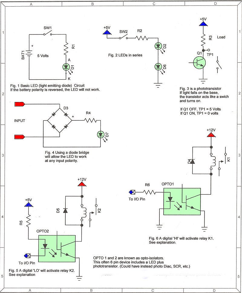
An opto-isolator is a solid state device designed to provide electrical isolation between input and output. The input consists of a light emitting diode (LED) in a six or eight pin dip (IC) package depending on type. The output can be a photo transistor, photo Diac, etc. There is no electrical contact between input and output.
When the LED is turned on, the Diac, transistor, etc. will conduct from the light emitted from the diode thus turning on the triac like a switch. The MOC3011 series is made to connect to triacs, the MOC301x types for 110 volts, and the MOC302x types for 240 volts. View the schematic.
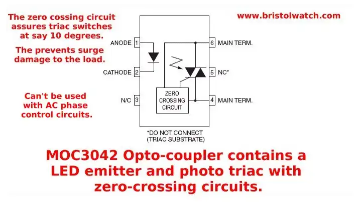
(above) MOC3042 Other opto-couplers have a built in zero-crossing detector.
Snubbers
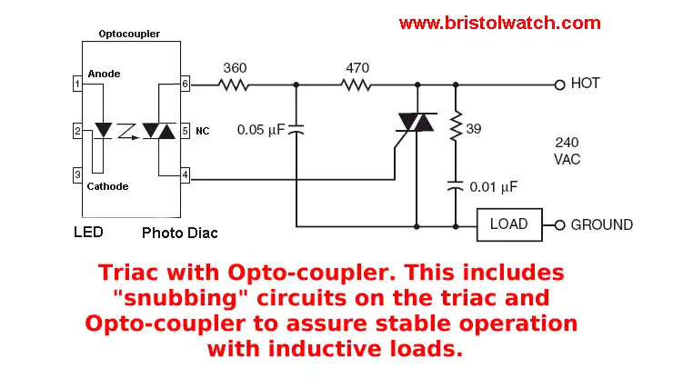
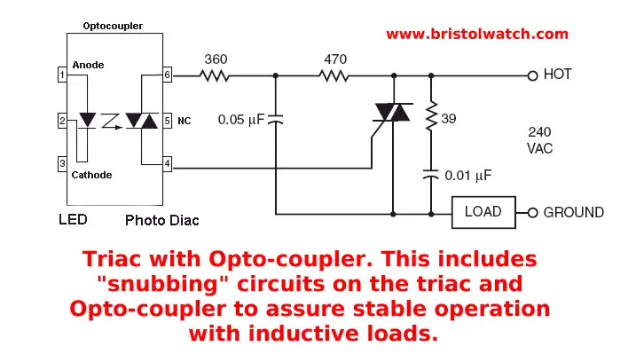
A snubber circuit (usually of the RCA type) is often used between Mt1 and Mt2. Snubber circuits are used to prevent premature triggering caused for example by voltage spikes in the AC supply or those produced by inductive loads such as motors.
Also, a gate resistor or capacitor (or both in parallel) may be connected between gate and Mt1 to further prevent false triggering. That could increase the required trigger current and perhaps a delay in turnoff as the capacitor discharges.
In this circuit above the "hot" side of the line is switched and the load connected to the cold or ground side. The 39-ohm resistor and 0.01uF capacitor are for snubbing of the triac, and the 470 ohm resistor and 0.05 uF capacitor are for snubbing the coupler. These components may or may not be necessary depending upon the particular and load used.
For more on the above opto-coupler see moc30xx series opto-isolator and MOC3042 with zero-crossing circuits. (both pdf files)
- Quick navigation of this website:
- Basic Electronics Learning and Projects
- Basic Solid State Component Projects
- Arduino Microcontroller Projects
- Raspberry Pi Electronics, Programming
- ULN2003A Darlington Transistor Array with Circuit Examples
- Tutorial Using TIP120 and TIP125 Power Darlington Transistors
- Driving 2N3055-MJ2955 Darlington Transistors
- Understanding Bipolar Transistor Switches
- N-Channel Power MOSFET Switching Tutorial
- P-Channel Power MOSFET Switch Tutorial
- H-Bridge Motor Control with Power MOSFETs
- Arduino Controlled IR2110 Based H-Bridge HV Motor Control
- IGBT Based High Voltage H-Bridge DC Motor Control
- More Power MOSFET H-Bridge Circuit Examples
- Build a High Power Transistor H-Bridge Motor Control
- Related:
- N-Channel Power MOSFET Switching Tutorial
- P-Channel Power MOSFET Switch Tutorial
- Test Power MOSFET Transistors, Observations
- Issues on Connecting MOSFETs in Parallel
- Basic MOSFET Transistor Test Circuits
- High Voltage MOSFET Switching Circuits
- Why Your MOSFET Transistors Get Hot YouTube
- Issues on Connecting MOSFETs in Parallel YouTube
- Simple Circuits for Testing MOSFET Transistors YouTube
See the following spec sheets:
- Basic Triacs and SCRs
- Constant Current Circuits with the LM334
- LM334 CCS Circuits with Thermistors, Photocells
- LM317 Constant Current Source Circuits
- TA8050P H-Bridge Motor Control
- All NPN Transistor H-Bridge Motor Control
- Basic Triacs and SCRs
- Comparator Theory Circuits Tutorial
Web site Copyright Lewis Loflin, All rights reserved.
If using this material on another site, please provide a link back to my site.