Basic Power Transformers
by Lewis Loflin
In this section we will explore a broad number of topics related to transformers. This will be limited to mostly power transformers, their operation, and how to use/test them. I will assume the reader has a basic knowledge of DC and Ohms Law along with basic magnetics. If one needs to review these subjects see the following:
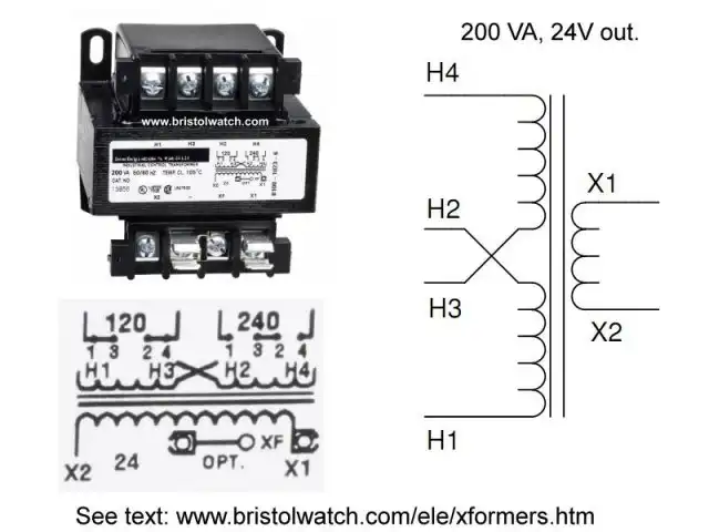
In diagrams above a basic transformer consists of at least two coils of wire wound on an iron core. The pulsating magnetic field produced in the primary by the AC induces a voltage in the secondary as the expanding and collapsing magnetic field from the primary cuts across the secondary winding.
The voltage output from the secondary is proportional to the input voltage and the ratio of primary windings (number of turns) to secondary windings.
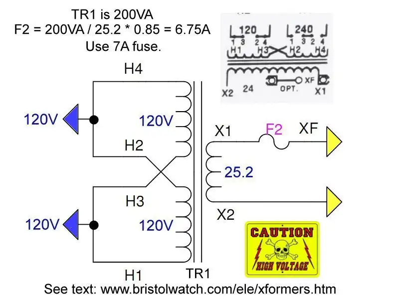
Transformer connected for 120V input.
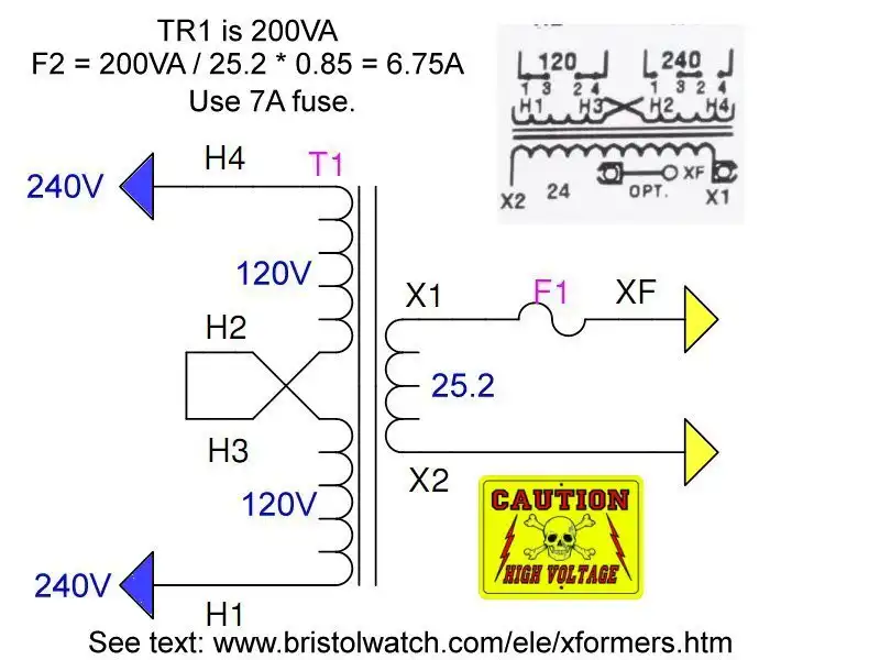
Transformer connected for 240V input.
Transformers are sized by determining the total load required (in amps). Transformer capacity is rated in KVA (kilo-volt-amperes). The load voltage and load amps must be known to calculate KVA rating.
NOTE: We do not recommend loading a transformer above 80% of its KVA rating. When the KVA rating has been calculated, divide that number by 0.8 to get the minimum KVA rating needed.
Example 1: I need 24VAC at 30A; 24 * 30 = 720 VA / 1000 = 0.720 KVA; 0.720 KVA/ 0.8 = 900 VA. Use a 1 KVA transformer.
Example 2: I have a 1 KVA transformer. What are my max amps at 24V? First multiply 1 KVA * 0.8 = 800 VA; then divide 800 VA by 24V = ~33A
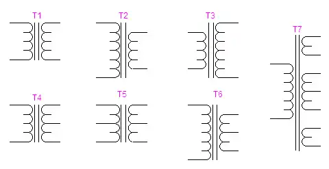
Figure 1 Basic types of transformers.
In figure one above is the basic electrical symbol for a transformer. The basic transformer consists of at least two coils of wire wound around an iron core. While there are many variations those above are:
T1: a one-to-one isolation transformer. The voltage in is the same as the voltage out. These are used to isolate the "hot" side of the power line from the user on the secondary side. In fact except for auto transformers, this is a property of all transformers is electrical isolation between primary and secondary.
T2: basic step down transformer. The number of windings in the primary are greater than the number of windings in secondary producing a lower output voltage than the input voltage. The step down voltage is based on the ratio of the primary windings to the secondary windings.
T3: basic step up transformer. The number of windings in the primary are less than the windings in the secondary. The step up voltage is based on the ratio of the primary windings to the secondary windings.
T4: transformer with center-tapped secondary. The voltage measured from the center tap connection to either end should read the same.
T5: transformer with center tapped primary and secondary.
T6: step down transformer with center-tapped secondary. This is how the common "pole transformer" that supplies power for a house is constructed.
T7: transformer with multiple secondaries. The individual windings can be any combination of step up or step down.
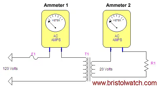
Figure 2
Voltage and Current in Power Transformers
In the figure we have a theoretical transformer with 120 volts AC input and 20 AC output at one amp (I). Let's assume resistor R1 is 20 ohms. How much current will flow through fuse F1? In this case we have a windings ratio of 120:20 = 6:1.
To solve these type of problems I use a formula of power in equals power out. (I'll address losses shortly.) In the secondary resistor R1 is 20 ohms (R) and at 20 volts (E), so E/R = I; 20/20 = 1 amp. Power = E*I = 20*1 = 20 watts. So in this problem the secondary consumes 20 watts, so the primary must supply 20 watts. In the above example 1 amp flows through ammeter 2.
In the primary we know the input voltage (E) is 120 volts and the power to be supplied (P) is 20 watts. To find the current (I) we use the formula P/E = 20/120 = 0.167 amps or 167 mA. That is also the current through ammeter 1 and the fuse, so we should use a fuse no greater than a standard 1/4 amp fuse for safety.
This seems to confuse many students that so little current with a much higher voltage can be the same power level as a high current at a low voltage. We are talking power the product of current and voltage, not just voltage or current alone.
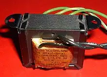
Laminated core transformer showing
edge of laminations at top of the picture.
Does the primary just supply only 20 watts to deliver 20 watts to the load? The answer is no, more likely 23 watts. There are losses in transformer itself, at least a few watts in this simple circuit. There are three general types of power losses in transformers:
Hysteresis: resistance in change to magnetic fields in magnetic material. In other words the iron core in the transformer resists the change in magnetic fields caused by the AC current. The iron molecules resists the bending caused by the magnetic field producing waste heat.
Eddy currents: small current flow induced in the iron core of the transformer. The transformer core often consists not of solid iron/steel but laminated sheets bonded together. There are several other types of magnetic losses I won't go into.
Copper losses: heating caused by the resistance of the copper wire in the windings. The term is applied regardless of whether the windings are made of copper or another conductor, such as aluminum. Hence the term winding loss is often preferred.
Copper losses result from Joule heating and so are also referred to as "I squared R losses", in deference to Joule's First Law. This states that the energy lost each second, or power, increases as the square of the current through the windings and in proportion to the electrical resistance of the conductors.
Copper Loss = I*I*R where I is the current flowing in the conductor and R the resistance of the conductor. With I in amperes and R in ohms, the calculated power loss is given in watts.
The more current through the wire the higher the losses due to heat. In addition the resistance of copper wire (and most metals) increases with temperature. Using figure 2 as an example with one amp we do have losses in the wire, but the same wire at two amps will produce four times the losses (as heat) of one amp!
The resistance of the copper is directly related to the diameter (gauge) of the wire and its length. For example AWG 28 gauge wire has a resistance of 64.9 ohms per 1000 feet of wire and a wire diameter of 0.013 inch. AWG 12 gauge has a resistance of 1.588 ohms per 1000 feet and a wire diameter of 0.081 inch. This is used in house wiring and can carry 41 amps while AWG 28 can only carry 1.4 amps.
Note: the higher the AWG number the thinner the wire. In other terms AWG 28 can carry enough current to safely operate a 150 watt light bulb at most while AWG 12 can carry the current to safely operate a large microwave oven or 3600 watt electric room heater.
Looking at our transformer above in figure 2 we have we have a primary current of 0.167 amps and a secondary current of 1 amp. It's obvious we can use a smaller diameter wire in the primary than the secondary.
When a transformer is designed the wire gauges used in the primary and secondary are often as thin as possible to reduce cost while carrying the specified current. But thinner wire has more resistance than heavier gauge wire. This we have to consider in choosing a transformer.
Let's argue our transformer figure 2 measures 50 ohms in the primary and 2 ohms in the secondary. How much power will be lost due to copper loss?
For the primary: I*I*R = 0.167 * 0.167 * 50 = 1.39 watts.
For the secondary: I*I*R = 1 * 1 * 2 = 2 watts.
Total watts lost to copper loss = 3.39 watts plus about 2 watts in various magnetic losses. With a 20 watt transformer that is a considerable loss at almost 22%. Using larger gauge wire (at higher cost) to reduce this heating is vital. In reality a good transformer is often over 95% efficient.
To summarize wire gauge is directly related current carrying capacity. Voltage is related quality of the electrical insulation. Power is the product of voltage and current. If we transfer power at a higher voltage but at less current, we can deliver power at lower cost by using a smaller gauge wire. Let's explore this in more detail.
As a final note these reading may not be accurate as such. Transformers are inductive devices where inductive reactance will skew AC readings.
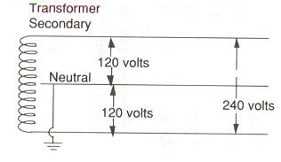
Transformers Supply Power to the Home
Without the use of transformers modern electrical power would be impossible or far more expensive. Here I'll look at the modern home and how transformers are used. (The examples below may not be up to local codes and are examples only.)
Again power is a product of voltage and current. (E*I) A modern home electrical service is 200 amps at 240 volts. (Take a look at ones home breaker box.) If using an overhead line, the wiring from the weather head where the power company connects to the home down to the breaker box itself often uses AWG 00 wire.
If copper it can carry 283 amps free air, plenty for a 200 amp service. But this is very expensive wire with a diameter of 0.365 inch and a weight of 403 pounds per 1000 feet.
A mile of this wire would weigh over one ton and that's just for one 200 amp service at one home. Aluminum wire is cheaper, but has to be a larger diameter to carry the same current as copper. The cost here with both would be prohibitive.
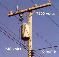
The solution is the use of transformers. When power is generated the voltage is stepped up to a transmission voltage as high as 400,000 volts for long distances. One can use a much smaller (thus cheaper and lighter) gauge wire to carry power to a local substation. Here the high voltage is stepped down to a distribution voltage of 7200 volts to homes and businesses.
Pictured above is a typical single phase pole transformer. At the top of the pole is 7200 volt distribution voltage while the output utilization voltage is 240 volts.
A 200 amp service for a home can consume 48,000 VA (E*I) or 48 KVA. A 150 KVA transformer can service three homes or easily supply 600 amps for three homes. These would be very short runs of wire over three different conductive paths.
Even 1000 feet of AWG 00 has 0.0799 ohms thus say 100 feet at 200 amps would produce little losses in power. More likely for such a short run they would use say AWG 10 at 1.2 ohms per 1000 feet. 1000 feet of AWG 10 weighs about 30 pounds.
Note in the picture above the higher voltage wire at the top of the pole is thinner than the secondary side going to the three homes. What gauge wire could I use to carry the 7200 volts to feed the pole transformer? To supply 150 KVA at 7200 volts, the top conductors would have to carry about 21 amps.
This could be carried by AWG 14 with a diameter of 0.064 inches with 2.5 ohms resistance per 1000 feet. Total weight for 1000 feet of wire is under 13 pounds. (I assume minus the weight of the insulation.) Thus of the 150,000 watts we would lose about 52 watts to copper losses per 1000 feet of wire.
Finally the transformer has a turns ratio of 7200:240 = 30:1.
- Basic Power Transformers
- Connecting Transformers in Series-Parallel
- Voltage Buck-Boost Transformer Connections Tutorial
- Connecting Industrial Control Transformers Examples
- Quick navigation of this website:
- Basic Electronics Learning and Projects
- H-Bridge Motor Controls
- Transistor Switching Circuits
- Power Supplies Projects
- Switching Power Supply Projects
- Battery Chargers with Arduino Controller
- Opto-Coupler, SCR, and Triac Circuits AC Power Control
- Zero-Crossing Detectors for AC Power Control with Arduino
- DIACs, SIDACs, and Unijunction Transistors Switching Circuits
- Xenon Flash Tube Circuits - High Voltage!
- Hall Sensors Circuits and Sensors for Magnetic Detection
- Comparator Circuit Examples
- Constant Current and Current Limiter Circuits
- Photo Diode Detector Circuits
- Digital Circuits and Projects
- Stepper Motor Operation and Control
- Crystal Radio, Odds and Ends Circuits
- Geiger Counters and Science Topics
- Popular Webpages & Corresponding Videos
- YouTube Videos List
- Off Site:
- Bristolblog an Alternative News Skeptic Site
- Web Master
- Tri-Cities VA-TN
- General Science
- US Constitution
- Christianity 101
- Religious Themes
Web site Copyright Lewis Loflin, All rights reserved.
If using this material on another site, please provide a link back to my site.