
Build a Thermocouple Amplifier
by Lewis Loflin
In 1821 Thomas Johann Seebeck discovered that a small voltage is produced when two different metals are joined together and the junction is heated. By adding a second junction at a lower temperature, the effect was even more pronounced. That difference increases with temperature, and is between 1 and 70 micro volts per degree Celsius (uV / degree C) for various metal combinations.
Thermocouples are used at much higher temperatures than thermistors, which change resistance with change in temperature, and don't produce a voltage at all.
This is a better way to use a thermal couple: Simple 3-Wire MAX6675 Thermocouple ADC Arduino Interface
How the Thermocouple Works on Gas Furnaces
A thermocouple (technically called a thermocouple junction) is a device that contains two differing metal wires welded at the ends and placed inside a protective metal (often steel) case. The thermocouple sensor is inserted into the pilot flame and is designed to be placed in the hottest part of the flame. The other end is connected to the pilot's electromechanical valve.
As the thermocouple heats up, it produces a small amount of voltage and when it gets hot enough, the voltage will open the gas valve by using a solenoid operated by a 24 volt transformer. The thermocouple by converting heat to an electrical signal, it allows the gas valve to open or close.
Once the gas valve is open, gas is then constantly supplied to the pilot and as required for the gas burners (as called for by the thermostat). If the pilot goes out, then the thermocouple gets cold and produces no electric signal to open the gas valve's solenoid and the gas valve shuts off the gas supply to the pilot and burners. If the thermocouple fails or the pilot goes out, the valve remains closed shutting down the system.
While a typical thermocouple produces a voltage of around 30 mV, a thermopile will produce 750 mV enough to operate a sensitive gas valve without use of a 24-volt transformer or connection to a power line. I know the 30 mV models can be bought at Lowes or Home Depot, not sure about the thermopile. More likely a camper supply could get them.
One could buy one and experiment with them. They would be more reliable, but where is the fun in that? For more on thermocouple theory see thermocouple.pdf.
Build Your Own
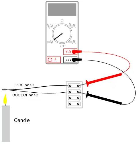
INSTRUCTIONS: Twist one end of the iron wire together with one end of the copper wire. Connect the free ends of these wires to respective terminals on a terminal strip. Set your voltmeter to its most sensitive range and connect it to the terminals where the wires attach. The meter should indicate nearly zero voltage.
What you have just constructed is a thermocouple: a device which generates a small voltage proportional to the temperature difference between the tip and the meter connection points. When the tip is at a temperature equal to the terminal strip, there will be no voltage produced, and thus no indication seen on the voltmeter.
Light a candle and insert the twisted-wire tip into the flame. You should notice an indication on your voltmeter. Remove the thermocouple tip from the flame and let cool until the voltmeter indication is nearly zero again.
Now, touch the thermocouple tip to an ice cube and note the voltage indicated by the meter. Is it a greater or lesser magnitude than the indication obtained with the flame? How does the polarity of this voltage compare with that generated by the flame?
After touching the thermocouple tip to the ice cube, warm it by holding it between your fingers. It may take a short while to reach body temperature, so be patient while observing the voltmeter's indication.
A thermocouple is an application of the Seebeck effect: the production of a small voltage proportional to a temperature gradient along the length of a wire.
This voltage is dependent upon the magnitude of the temperature difference and the type of wire. Directly measuring the Seebeck voltage produced along a length of continuous wire from a temperature gradient is quite difficult, and so will not be attempted in this experiment.
Thermocouples, being made of two dissimilar metals joined at one end, produce a voltage proportional to the temperature of the junction.
The temperature gradient along both wires resulting from a constant temperature at the junction produces different Seebeck voltages along those wires' lengths, because the wires are made of different metals. The resultant voltage between the two free wire ends is the difference between the two Seebeck voltages:
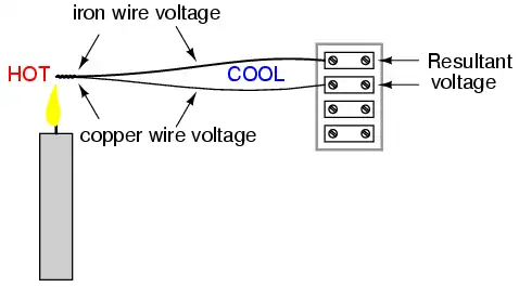
Thermocouples are widely used as temperature-sensing devices because the mathematical relationship between temperature difference and resultant voltage is both repeatable and fairly linear. By measuring voltage, it is possible to infer temperature. Different ranges of temperature measurement are possible by selecting different metal pairs to be joined together.
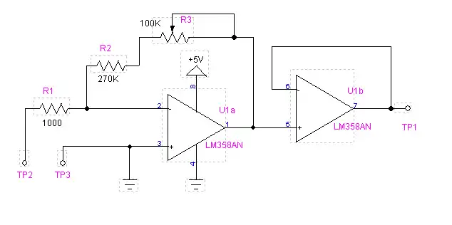
Note changing the 5-volts to 6-7 volts or higher gives a full 0-5V output.
Because the voltage from a thermocouple is so small, it may be difficult to measure. Pictured above is a working and tested thermocouple amplifier using a Lm358 single voltage dual op-amp. The gain is from 50 to about 150 depending on the adjustment of R3. My test thermocouple (a commercial unit) put out a maximum voltage of 20 mV produced 3.8 volts output at s-volts.
Connect negative side of the thermocouple to TP2 and the positive side to TP3.
Also note this circuit can be connected to 12 volts instead of 5 volts. Change R2 to 1000 ohms and R3 to 1 meg. On the highest output (8.6 volts or so) on the thermocouple adjust R3 for about 5 volts max. Don't drive the op-amp above 5.1 volts output at TP1 if going to a micro-controller.
Observe voltage polarity on the input. If noise is a problem, connect a .001 uF from Vin to ground.
Published under the terms and conditions of the Creative Commons Attribution License
Ref. http://www.allaboutcircuits.com/
Copyright 1999-2000 Michael Stutz stutz@dsl.org
![]()
- Quick navigation of this website:
- You Tube Channel
- Basic Electronics Learning and Projects
- Basic Solid State Component Projects
- Arduino Microcontroller Projects
- Raspberry Pi Electronics, Programming
- Basic Triacs and SCRs
- Constant Current Circuits with the LM334
- LM334 CCS Circuits with Thermistors, Photocells
- LM317 Constant Current Source Circuits
- TA8050P H-Bridge Motor Control
- All NPN Transistor H-Bridge Motor Control
- Basic Triacs and SCRs
- Comparator Theory Circuits Tutorial
- Comparator Theory Circuits Tutorial
- Arduino Projects Revisited Revised
- Schematic for Following Projects
- Programming ADS1115 4-Channel I2C ADC with Arduino
- Arduino uses ADS1115 with TMP37 to Measure Temperature
- Connect Arduino to I2C Liquid Crystal Display
- Arduino Reads Temperature Sensor Displays Temperature on LCD Display
- Arduino with MCP4725 12-bit Digital-to-Analog Converter Demo
Web site Copyright Lewis Loflin, All rights reserved.
If using this material on another site, please provide a link back to my site.