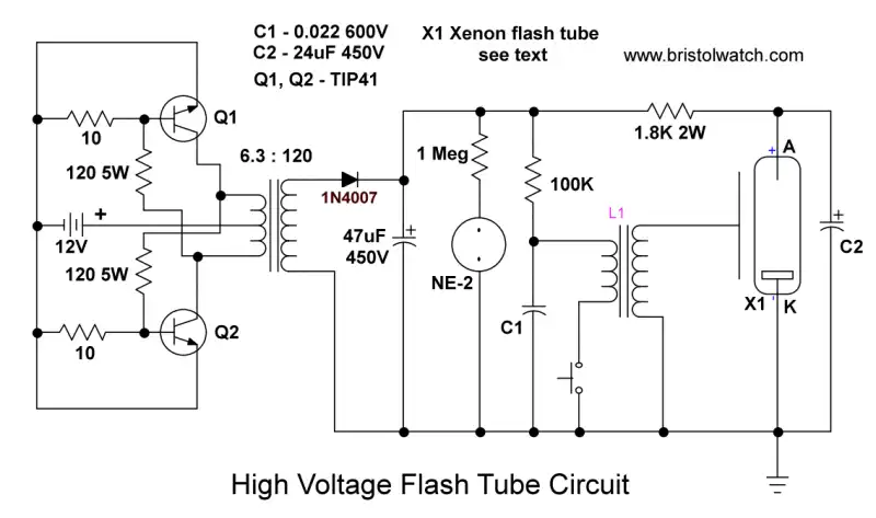
Fig. 1
Simple 12-14 Volt DC to High Voltage AC Inverter
by Lewis Loflin
Fig. 1 illustrates using an inverter circuit to power a 300-volt xenon flash tube.
The inverter pictured above uses only four resistors and two transistors, and one transformer. While pictured using NPN transistors, PNP transistors could be used as long as one reverses the battery polarity. I have used both the 2N3055 and TIP41A with R1, R2 at 220 ohms. Make sure the transistors are heat sinked.
Note to use this circuit to create 300 volts for flashtubes use a 6-volt center-tapped transformer. See flashtubes.
The key to the voltage output and frequency is the transformer. To get 120 VAC the transformer will have to be 24-volt center-tapped. If using a 12-volt center-tapped transformer the voltage will be over 240 volts at 14 volts DC input.
This operates by the fact the two transistors won't be exactly alike so they switch each other on/off.
The frequency depends on the physical size of the transformer. Smaller transformers operate at a high frequency, large transformers at low frequency. One small transformer I used (9-volt center-tapped) produced over 300 volts at several thousand Hertz. This operated a four foot fluorescent lamp directly with no other parts. The same circuit with a larger (thus lower frequency output) failed to ionize the lamp.
The frequency will also change depending on the load. Be careful because one can really create some dangerous voltages if mishandled.
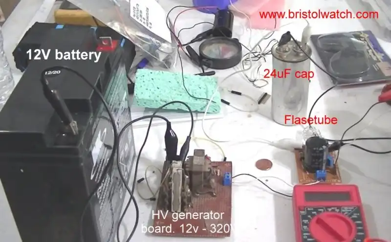
Fig. 2
Fig. 5 is the actual inverter power source circuit with a 12-volt battery. It powers a flash tube circuit.
YouTube video Transistor HV Generator.
See Unijunction Transistor SCR Photo Flash Control Circuit
![]()
- Quick navigation of this website:
- You Tube Channel
- Basic Electronics Learning and Projects
- Basic Solid State Component Projects
- Arduino Microcontroller Projects
- Raspberry Pi Electronics, Programming
- Simple 12-14 Volt DC to High Voltage AC Inverter for Flashtubes
- Understanding Xenon Flashtubes and Circuits
- Unijunction Transistor SCR Photo Flash Control Circuit
- Understanding Unijunction Transistors Theory Operation
- Used with photo flash circuits:
- How to use SIDACs and Their Operation
- SIDAC Controlled Flashtube and Pulse Circuits YouTube
- DIAC Waveform Generator, Trigger Circuits Part 1
- DIAC Relaxation Oscillator Pulse Generator Part 2
- Neon NE-2 Lamp Trigger Photoflash
- Unijunction Transistor SCR Photo Flash Control Circuit
- Constant Current Circuits with the LM334
- LM317 Constant Current Source Circuits
- Introduction Hall Effect Switches, Sensors, Circuits
- Using Ratiometric Hall Effect Sensors
- Pulse Width Modulation Power Control
- Introduction to PIC12F683 Programming
- Basic Transistor Driver Circuits
- Opto-Isolated Transistor Drivers
- Basic Triacs and SCRs
- Constant Current Circuits with the LM334
- LM334 CCS Circuits with Thermistors, Photocells
- LM317 Constant Current Source Circuits
- TA8050P H-Bridge Motor Control
- All NPN Transistor H-Bridge Motor Control
- Basic Triacs and SCRs
- Comparator Theory Circuits Tutorial
Web site Copyright Lewis Loflin, All rights reserved.
If using this material on another site, please provide a link back to my site.