Figure 1 very basic H-bridge.
MOSFET H-Bridge Motor Control
by Lewis Loflin
Permanent magnet DC motors have been around for many years and come in a variety of sizes and voltages. Their direction of rotation is dependant upon the polarity of the applied voltage. Reverse the voltage, the direction of rotation reverses. One of the most common solid-state controls is known as the H-bridge.
In figure 1 we have a very basic H-bridge using two spring-loaded, single-pole, double-throw switches. The normally closed (NC) contacts are grounded and normally open (NO) contacts are connected to +12 volts.
A DC motor is connected between the two commons. In its normal state, both motor connections are grounded through the switches. Both switches are spring loaded.
If we press SW1 the NC contact opens and the NO closes supplying +12 volts to one side of the motor while the other side is still grounded through SW2. The motor will rotate at full speed say counter-clockwise.
Release SW1 and press SW2 and +12 volts is supplied to the '+' side of the motor while the negative side is grounded through SW1. The direction now is clockwise. Press both switches and both sides of the motor will be at +12 volts and won't run.
Any number of solid-state switches can be used for H-Bridges. This depends on motor voltage and current that determines the H-Bridge construction. Here I emphasize power MOSFETs.
It is just as easy to use combinations of MOSFETs, bipolar transistors, and even insulated gate bipolar transistors.
Many micro-controllers today are using 3.3-volt Vcc. This is also true of Raspberry Pi. I found two MOSFETs that work at 3.3-volts.
The IRFZ44N is an N-channel device rated at 55V and RDS(on) resistance of 0.032 Ohms max.
The IRF4905 is a P-channel device rated at 55V and a RDS(on) of 0.02 Ohms max.
In building the following circuits I suggest using a current limiter on the power supply and a small motor. When it is working then move up to heavy motor.
Because I'm using opto-isolators the motor supply common can be separate from the microcontroller common.
See the following two larger size diagrams: H-Bridge Separate Power Supply Common and H-Bridge Power Supply Common.

Figure 2 MOSFET H-Bridge with motor voltage isolation.
In Fig. 2 illustrates how the use of opto-couplers OC1 and OC2 allows electrical isolation of motor voltage from the microcontroller circuits.
Figure 3 MOSFET H-Bridge with motor voltage common with control circuit.
Fig. 3 illustrates a common ground between microcontroller control circuits and the h-bridge common ground.
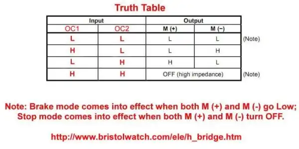
Figure 4 MOSFET H-Bridge control truth table.
This was based on a Toshiba TA8050P H-bridge. See the spec sheet ta8050p.pdf.
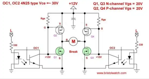
Figure 5 MOSFET H-Bridge motor control in break mode.
In break mode both sides of the motor are grounded through the lower N-channel MOSFETs. Counter EMF from the motor motion acts to break the motor direction of rotation..
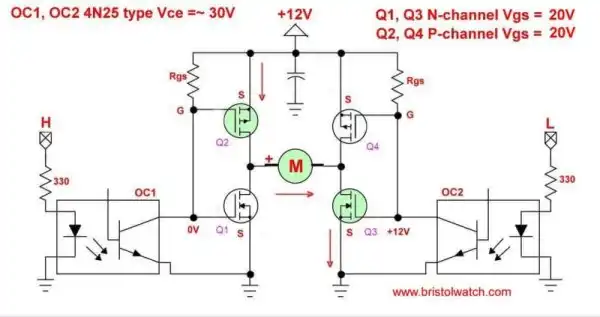
Figure 6 MOSFET H-Bridge motor control clockwise rotation.
When a HIGH turns on opto-coupler OC1, Q1 is turned off while Q3 is turned on. This creates a current path for the motor through Q2 and Q3. The motor will rotate I'll say clockwise.
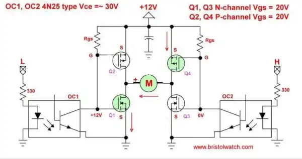
Figure 7 MOSFET H-Bridge motor control counter-clockwise rotation.
Here we turned off opto-coupler OC1 (turns Q1 on and Q2 off) and turned on OC2. This turns off Q3 and turns on Q4. Q1 and Q4 provide a current path for the motor, but in the opposite direction for the current flow. This results in counter-clockwise or reversal of rotation of the motor.
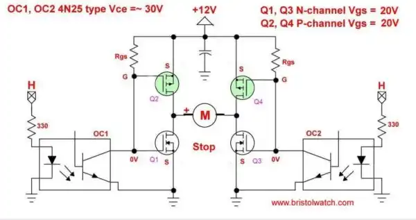
Figure 8 MOSFET H-Bridge motor control in stop mode.
Fig. 8 illustrates stop mode - the motor is simply turned off as Q2-Q4 are turned on while Q1-Q3 are turned off.
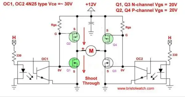
Figure 9 MOSFET H-Bridge motor control with shoot-through.
Now I'll address the problem of shoot through. This is a condition where a transistor, let's say Q2, has not switched fully off as Q1 is switched on. This creates power supply overload and possible damage to MOSFETs. I've used this circuit without problem, but we can't ignore this problem.
This can be a particular risk with high speed motor direction change or using pulse-width modulation to control motor speed.
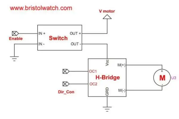
Figure 10 MOSFET H-Bridge motor control with motor power on-off control.
Fig. 10 illustrates the use of a motor power switch to turn off a generic h-bridge circuit. Based on the above schematics simply switch motor voltage off, change direction, then motor voltage back on. That prevents any chance of shoot-trough. We can also pulse-width modulate the switch to control motor speed.
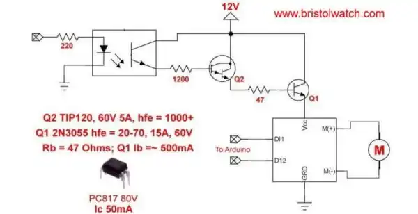
Figure 11
Fig. 11 illustrates a possible power switch circuit.
The circuit above: Design 10-Amp 2N3055 Based Power Switch
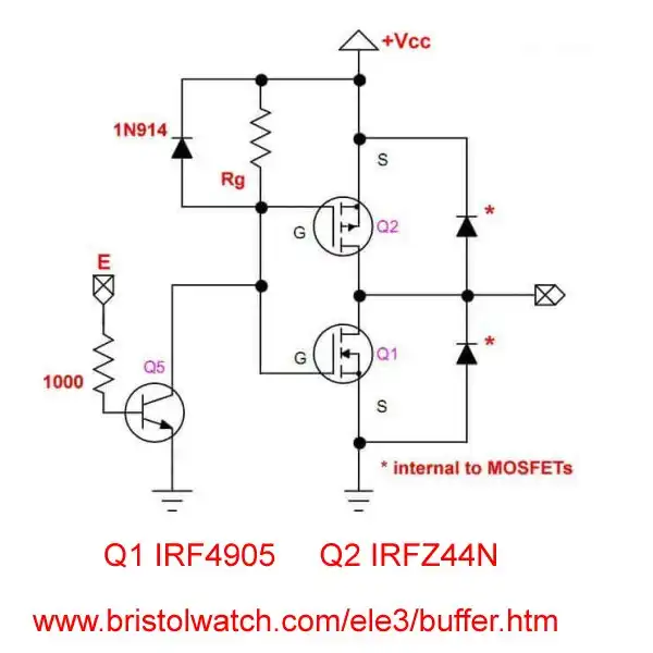
Figure 12
Now I will address other issues.
I will be normal for the p-channel MOSFET to get hotter than the n-channel. This is due to higher DS-on resistance of the p-channel.
Rb serves to discharges the gate-source circuit to turn off Q2. In the past I used a 10K resistor, it can be dropped to 1000 ohms. This can result in faster turn off.
The 1N914 diode across Rb suppresses any gate-source discharge noise with Rb.
Finally we can use a NPN transistor instead of an opto-coupler.
- Quick navigation of this website:
- Basic Electronics Learning and Projects
- Basic Solid State Component Projects
- Arduino Microcontroller Projects
- Raspberry Pi Electronics, Programming
- Opto-Isolated transistor driver circuits.
- Transistor Driver Circuits
- Opto-Isolated Transistor Drivers
- Optical Isolation of H-Bridge Motor Controls
- MOSFET Transistors, IGBTs Observations
- Example H-Bridge Circuits
- L298N Motor Controller Theory and Projects
- Connecting the Arduino to a L298N H-Bridge
- All NPN Transistor H-Bridge Motor Control
- IGBT Based High Voltage H-Bridge DC Motor Control
- Arduino Controlled IR2110 Based H-Bridge HV Motor Control
- Tri-State H-Bridge using CD4093B CMOS Circuit
- CMOS-MOSFET H-Bridge Circuit
- Interfacing Arduino to CMOS and MOSFET Circuits
- Transistor circuits:
- ULN2003A Darlington Transistor Array with Circuit Examples
- Tutorial Using TIP120 and TIP125 Power Darlington Transistors
- Driving 2N3055-MJ2955 Power Transistors
- Understanding Bipolar Transistor Switches
- N-Channel Power MOSFET Switching Tutorial
- P-Channel Power MOSFET Switch Tutorial
- More Power MOSFET H-Bridge Circuit Examples
- Build a High Power Transistor H-Bridge Motor Control
- MOSFET-Transistor Drivers with TC4420 and TC4429, IGBTs, etc.
- Introduction TC4420-TC4429 MOSFET Drivers
- Use TC4420 MOSFET Driver for Simple H-Bridge Circuit
- TC4420 MOSFET Driver Various Circuits
- TC4420 MOSFET Driver Replacement Circuits
- Test Power MOSFET Transistors, IGBTs
- Insulated Gate Bipolar Transistor IGBT Circuits
- Issues on Connecting MOSFETs in Parallel
- Easy Driver Micro-Stepper Controller to Arduino
- Unipolar Stepper Motor with a Arduino
- MC3479 Stepper Motor Controller with Arduino
- Considerations for Using Stepper Motors
- Connecting the Arduino to a L298N H-Bridge
- L298N Motor Controller Theory and Projects
- TA8050 H-Bridge Motor Controller
- Using Hall Effect Switches and Sensors
- ULN2003A Darlington Transistor Array with Circuit Examples
- Tutorial Using TIP120 and TIP125 Power Darlington Transistors
- H-Bridge Motor Control with Power MOSFETs
- More Power MOSFET H-Bridge Circuit Examples
- Build a High Power Transistor H-Bridge Motor Control
Web site Copyright Lewis Loflin, All rights reserved.
If using this material on another site, please provide a link back to my site.