Fig. 1
TL431 Shunt Regulator Circuits
by Lewis Loflin
While the TL431 is an excellent shunt regulator, its current range is limited to 100mA. The addition of a PNP shunt transistor greatly increases power handling capability.
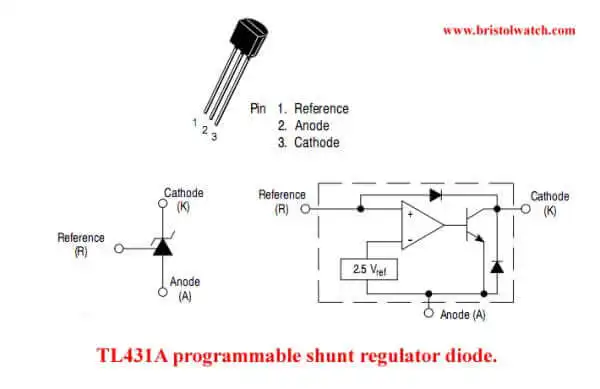
In simple terms the TL431A acts a temperature compensated variable/adjustable Zener diode. It can also act as a voltage reference. In addition to good temperature compensation and stability, the TL431A has a voltage range of 2.5 volts to 36 volts and a current range from 1mA to 100mA.
For basic information on the TL431 see Experiments with TL431A Shunt Regulator
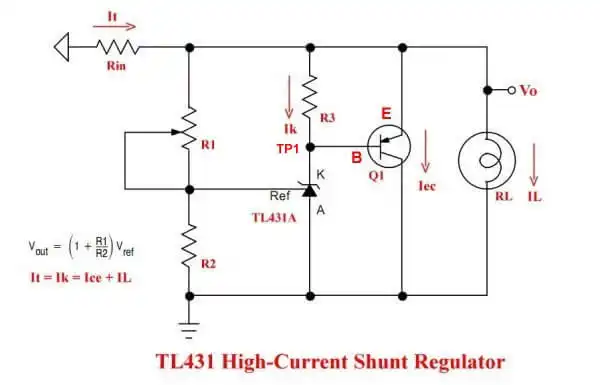
Fig. 2 Basic TL431 shunt regulator circuit example 1.
The TL431 is an excellent shunt regulator, but its current range is limited to 100mA. The addition of a PNP shunt transistor greatly increases power handling capability.
The output voltage on the TL431 cathode voltage (TP1) is determined by 2.5 * (1 + R1/R2). The voltage difference between TP1 and VOUT determined the current flow shunted though Q1 to ground.
The current from RIND is split between the TL431 (Ik), Q1 (Ice), RL (IRL). RIN should be carefully chosen as I will illustrate.
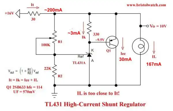
Fig. 3 Basic TL431 shunt regulator circuit example 2.
Fig. 2 reveals the problem created when RIN is too large. With a 30-ohm 10-watt resistor the maximum current this could supply with 10-volt VOUT is 200mA. With the load consuming 167mA (IL) this leaves little current to regulate the output voltage.
A little heavier load or voltage drop in the input voltage would mean no voltage regulation from the TL431-Q1 combination. The voltage drop across the 330-ohm resistor controls the current through Q1.
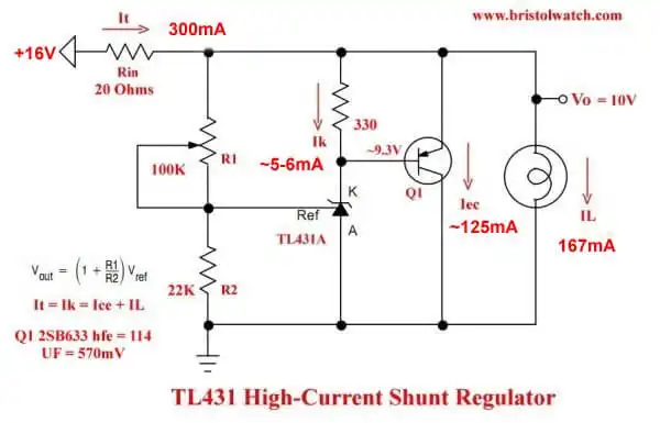
Fig. 4 Basic TL431 shunt regulator circuit example 3.
Fig. 3 shows a correct value of RIN at 20-ohms. With VOUT adjusted to 10-volts IRIN (with 16V input) =~ 6 / 20 = 300mA available. The load IL is still 167mA while the remaining current is split between Ik and Q1.
- Experiments with TL431 Shunt Regulator
- TL431A Precision Current Regulator Circuits
- TL431A Based Current Limiter Constant Current Source Circuits
- TL431A Shunt Regulator Circuits
- Using TL431A Li-Ion Battery Charger Tutorials
- TL431A Lithium-Ion Cell Charging Circuits
- Charging Multi-Cell Lithium-Ion Battery Packs
- TL431 Over-Voltage, Under-Voltage Detector Circuits
- TL431A Constant Current Source Working Circuits Demo
Related YouTube video TL431A Lithium-Ion Cell Charging Circuits
Related YouTube video TL431 Battery Charger Circuit Calculations Revised
Related YouTube video TL431 10-Volt Charger Short Version
Related YouTube video Charging, Charge-Balancing 18V Li-Ion Battery with TL431
Related YouTube video 18.5V Li-Ion Battery Charger with TL431 (short)
- Arduino Measures Current from Constant Current Source
- Constant Current Source Theory Testing
- Arduino Controlled Power Constant Current Source
- LM317 Adjustable Current Boost Power Supply
- Constant Current Circuits LM334, LM317
- Build LM317 0-34 Volt Power Supply
- LM334 Constant Current Source with Resistive Sensors
- LM317 High Power Constant Current Source Circuit
- LM317 Constant Current Source Circuits
- Test SCRs and Triacs
- Basic MOSFET Transistor Test Circuits
- High Voltage MOSFET Switching Circuits
- 3 Amp LM741 Op-Amp Constant Current Source
- Current Limiter Testing of Zener Diodes
- Current Limiter for Opto-Coupler Inputs
- LM317 CCS for Light Emitting Diodes
Other Circuits
- Hall Effect Magnetic Switches and Sensors
- Comparator Theory Circuits Tutorial
- ULN2003A Darlington Transistor Array with Circuit Examples
- Transistor-Zener Diode Regulator Circuits
- AC Power Supply Rectification
- Coils for Highly Selective Crystal Radio
- Neon (NE-2) Circuits You Can Build
- Photodiode Circuits Operation and Uses
- Photodiode Op-Amp Circuits Tutorial
Web site Copyright Lewis Loflin, All rights reserved.
If using this material on another site, please provide a link back to my site.