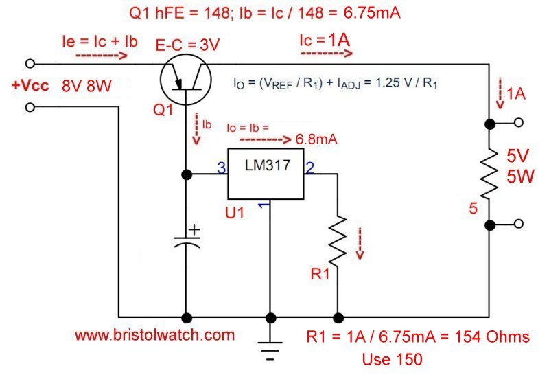
Fig. 1 LM317 controls MJ2955 transistor creating a 10-amp constant current source.
LM317 High Power Constant Current Source Circuit
by Lewis Loflin
Follow @Lewis90068157
A constant current source (CCS) in electronics is a device/circuit that produces a constant value of current regardless of source voltage or load resistance. A constant current circuit can also be used as a current limiter.
This is also designed to limit circuit damage for developing other devices such as an H-Bridge.
This current limiter function is used in battery charging, the main focus of this tutorial.
In this circuit we use a LM317 to control a MJ2955 15-amp PNP transistor. This transistor Q1 had a measured DC gain (hFE) of 148. This has been built and tested. A number of improvements will be added.
The LM317 forms a high power constant current source by controlling the emitter-base current of Q1 by using an LM317 CCS. The CCS current is shunted to ground.
R1 determines the current though the LM317 with the formula 1.25V / R1. To determine the values of R1 in this example divide the desired output current (1A) by the hFE of Q1 (148). This equals 6.75mA. Then divide 1.25V by 0.00675 equals ~150-Ohms.
Related videos:
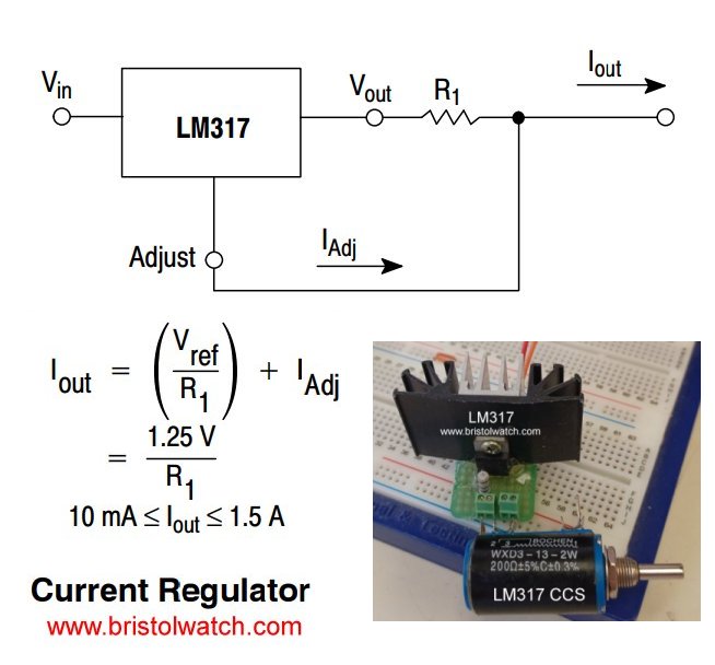
Fig. 2 1 amp LM317 constant current source image with heat sinks.
R1 can be replaced by a 10-Ohm resistor in series with a 200-Ohm 10-turn potentiometer as shown above. The heat sinks are not needed here as this particular unit not being used as a stand alone 1-amp adjustable constant current source.
An LM317 constant current source is controlling the base current (Ib) through a MJ2955 15 amp transistor. This combination supplies a far higher currant than the LM317 by itself.
The LM317T (TO-220 case) current is limited to 1.5A. This must be derated in the real world. Use the "70% rule" by multiplying by 0.70 the maximum rating in the spec sheet. 1.5A * 0.7 = ~1A.The diagram above taken from a live circuit test. The Q1 hFE was measured on a transistor checker.
The desired current of 2A with a transistor hFE of 148 is 2A / 148 = 13.5mA. Q1 with a DC gain (hFE) of 148 produces an output of 2 amps through a 10 ohm load.
Q1's base current (Ib) is set by the 200-Ohm potentiometer and 10 ohm combination to produce an Ib of 13.5mA. This can also be found by the formula 1.25 / Ib = 1.25 /0.0135 = ~92 Ohms. The nearest common resistor value is 91 Ohms.
See LM317 Constant Current Source Circuits
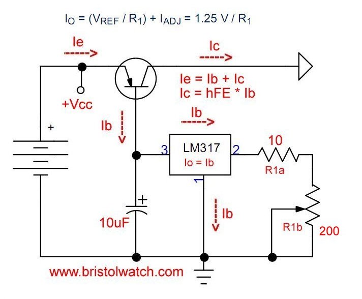
Fig. 3 Example using a potentiometer with a fixed resistor.
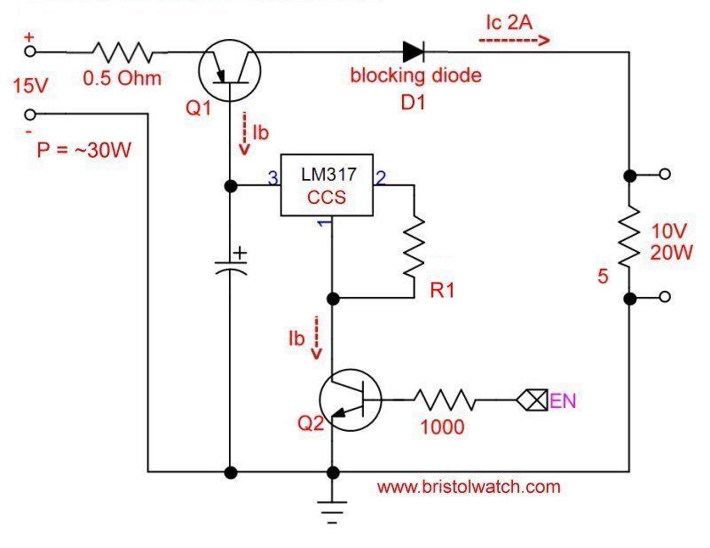
Fig. 4 LM317 constant current source with pass transistor as ON-OFF switch.
In Fig. 4 a number of changes have been added. Q2 acts as a current ON-OFF switch for the Q1-LM317 circuit. This can be controlled from an Arduino or similar microcontroller. A HIGH switches on Q2 completing the path to ground for the LM317.
See the following:
- Arduino Controlled Power Constant Current Source
- Arduino Measures Current from Constant Current Source
- Constant Current Source Theory Testing
An input ballast resistor is added from the positive supply input to Q1 emitter. As Q1 heats up the DC gain (hFE) will increase, thus the output current will increase. This could cause thermal runaway. The 0.5-Ohm resistor should counter this problem. This will be more useful when covering bipolar transistors in parallel.
D1 is a blocking diode needed if using this circuit for charging lead-acid or other batteries. This prevents battery current from feeding back into Q1 when the charging voltage is off.
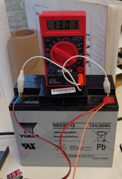
Fig. 5 12V Battery under charge with LM317 CCS and TL431 charge controller.
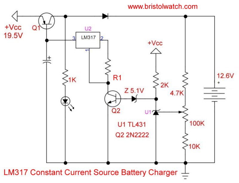
Fig. 6 12V Battery charger with LM17 CCS and TL431 charge controller.
In Fig. 6 the LM317 constant current source circuit have been paired with a TL431 under voltage detector circuit. This was used to charge a 12-volt lead-acid cell in Fig. 5.
See TL431 Over-Voltage, Under-Voltage Detector Circuits
The TIP120 can be replaced with a low power 2N2222, etc.
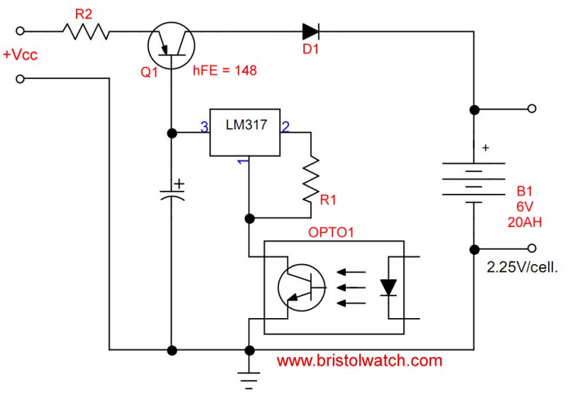
Fig. 7 LM317 transistor constant current source with optocoupler switch.
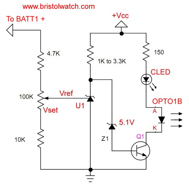
Fig. 8 TL431 voltage detector driving optocoupler LED.
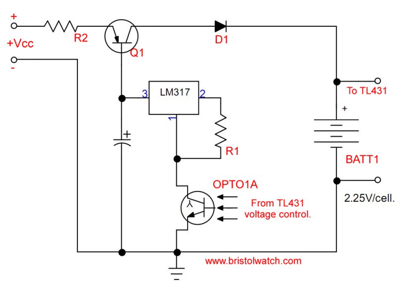
Fig. 9 LM317 switched ON-OFF through an optocoupler from TL431 voltage detector.
- Using TL431A Li-Ion Battery Charger Tutorials
- TL431A Lithium-Ion Cell Charging Circuits
- Charging Multi-Cell Lithium-Ion Battery Packs
- TL431A Constant Current Source Working Circuits Demo
- Power TL431 Constant Current Source Circuits
- TL431 Over-Voltage, Under-Voltage Detector Circuits
- LM317 Adjustable Voltage, Current Boost Power Supply
- Constant Current Circuits LM334, LM317
- Build LM317 0-34 Volt Power Supply
- LM334 Constant Current Source with Resistive Sensors
- LM317 High Power Constant Current Source Circuit
- LM317 Constant Current Source Circuits
- How to Test Silicon Controlled Rectifiers, Triacs
- Basic MOSFET Transistor Test Circuits
- High Voltage MOSFET Switching Circuits
- 3 Amp LM741 Op-Amp Constant Current Source
- Current Limiter Testing of Zener Diodes
- Current Limiter for Opto-Coupler Inputs
- LM317 CCS for Light Emitting Diodes
- Experiments with TL431 Shunt Regulator
- TL431A Precision Current Regulator Circuits
- TL431A Based Current Limiter Constant Current Source Circuits
- TL431A Shunt Regulator Circuits
- Using TL431A Li-Ion Battery Charger Tutorials
- TL431A Lithium-Ion Cell Charging Circuits
- Charging Multi-Cell Lithium-Ion Battery Packs
- TL431 Over-Voltage, Under-Voltage Detector Circuits
- TL431A Constant Current Source Working Circuits Demo
Related YouTube video TL431A Lithium-Ion Cell Charging Circuits
Related YouTube video TL431 Battery Charger Circuit Calculations Revised
Related YouTube video TL431 10-Volt Charger Short Version
Related YouTube video Charging, Charge-Balancing 18V Li-Ion Battery with TL431
Related YouTube video 18.5V Li-Ion Battery Charger with TL431 (short)
- Arduino Measures Current from Constant Current Source
- Constant Current Source Theory Testing
- Arduino Controlled Power Constant Current Source
You Tube Videos
- Adjustable LM317 High Power Current Source
- Current Boost LM317 Adj. Power Supply
- LM317 Constant Current Source Circuits
Other Circuits
- Hall Effect Magnetic Switches and Sensors
- Comparator Theory Circuits Tutorial
- ULN2003A Darlington Transistor Array with Circuit Examples
- Transistor-Zener Diode Regulator Circuits
- AC Power Supply Rectification
- Coils for Highly Selective Crystal Radio
- Neon (NE-2) Circuits You Can Build
- Photodiode Circuits Operation and Uses
- Photodiode Op-Amp Circuits Tutorial
Web site Copyright Lewis Loflin, All rights reserved.
If using this material on another site, please provide a link back to my site.