 Fig. 1
Arduino Motor Control Program Using IF
by Lewis Loflin
The two earlier tutorials will help with understanding this tutorial. See:
As a reminder of an "if" statement:
if (expression) true_do_this;
else false_do_this;
This tutorial will into more novel uses of the "if" statement.
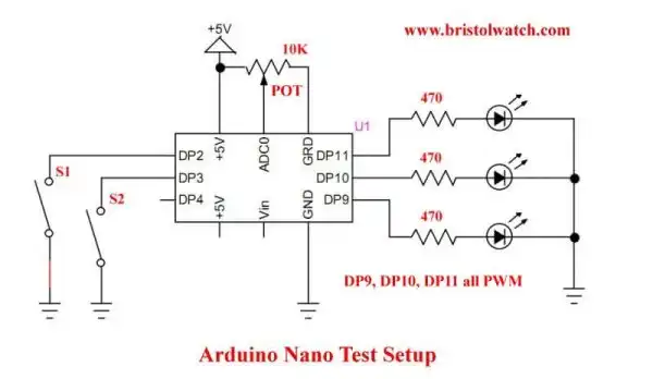
We will create a motor control program for an Arduino. Note the diagram above.
Ill assume the output pins for LED1 and LED2 connect to separate DC motors with driver transistors or to one on my many H-Bridge circuits.
LED3 could be connected to a power ON-OFF circuit. Or just use the LEDs.
What we want is 1) S1 turns on LED1; 2) S2 turns on LED2; 3) S1 and S2 together turn on LED3 ON or OFF. LED1 and LED2 should be disabled while LED3 is toggling between ON-OFF.
All three LED pins (DP9, DP10, DP11) all have pulse-width modulation (PWM) function. I'll use the function POT() to control LED brightness or motor speed. We could even PWM the power ON-OFF LED3.
I created function S1(), S2(), and POT() and are included in the template at the bottom of the page. The template also incorporates an I2C LCD display displaying switch values (1 or 0) and the potentiometer reading on from ADC0 which is returned when POT() is called.
ON is defined as 1 or HIGH; OFF is defined as 0 or LOW.
void loop() {
  delay(100);

  if ( POT() ) digitalWrite(LED1, ON);
  else digitalWrite(LED1, OFF);
}
Test 1
The function POT() reads the potentiometer connected to ADC0 on the Arduino. It returns an int value from 0-1023.
Observe line 2 of the LCD display "POT = 0" - set the control for 0. At position 0 POT() returns a 0 value when called making the "if" statement "false" turning OFF LED1.
Turn the potentiometer to any other value LED1 is ON. 1-1023 is interpreted as "true" thus LED1 is ON by the "if" statement except with 0.
The following line does the very same thing:
  if ( POT() != 0 ) digitalWrite(LED1, ON);
  else digitalWrite(LED1, OFF);
The following uses the NOT operator (!) to flip true to false, or false to true. Now LED1 is ON only at 0.
  if ( !POT() ) digitalWrite(LED1, ON);
  else digitalWrite(LED1, OFF);
The following turns on LED1 only when POT() is 700 or greater:
 if ( POT() >= 700 ) digitalWrite(LED3, ON);
 else digitalWrite(LED3, OFF);
The following turns on LED1 only when POT() is 700 or less:
 if ( POT() <= 700 ) digitalWrite(LED3, ON);
 else digitalWrite(LED3, OFF);
And so on Note the following comparison and Boolean operators:
Comparison Operators
== (equal to)
!= (not equal to)
< (less than)
> (greater than)
<= (less than or equal to)
>= (greater than or equal to)

Boolean Operators
&& (and)
|| (or)
! (not)
void loop() {
  delay(100);
  if ( (POT() >= 400) && (POT() <= 800) ) digitalWrite(LED3, ON);
  else digitalWrite(LED3, OFF);
} // end loop
Test 2
In the above code snippet we use a logical AND symbol "&&". (A single & is a bitwise function and will produce an error.)
I'm checking "expression" for true and both MUST be true for the "if" statement to be true. POT() must return a value from 400 AND to 800 to turn on LED3.
I would suggest using individual parentheses for each "expression" inside the "if" parentheses. While in this case it compiled and worked fine, other times it could compile fine but be wrong.
With this in mind let us get to the good stuff.
 Fig. 2
Fig. 2 is my motor test setup. For either motor to run DP11 (LED3) must be ON turning on Q3.
DP9 (LED1) must be ON to turn on Q1 and MOT1 runs forward. DP10 (LED2) must be ON to turn on Q2 so MOT2 runs in reverse.
void loop() {

  if ( S1() && !S2() ) {
    delay(200);
    if (S2()) { } // do nothing
    else digitalWrite(LED1, ON);
  }
  else digitalWrite(LED1, OFF);

  if ( S2() && !S1() ) {
    delay(200);
    if ( S1() ) { } // do nothing
    else digitalWrite(LED2, ON);
  }
  else digitalWrite(LED2, OFF);

  if ( S1() && S2() ) {
    byte temp = !digitalRead(LED3);
    digitalWrite(LED3, temp);
    while( S1() || S2() ) { } // do nothing
  } // end if

  POT(); // update LCD display


} // end loop
Test 3
The above program uses two switches and has 3 outputs. Both S1 and S2 must be pressed together to enable motor power control Q3 ON or OFF.
Then either S1 or S2 will enable their respective motors. Both motors (or LEDs) can't be operated at the same time. Either S1 or S2 will check if the other switch is pressed and if it is the rest of the statement is skipped.
That is the purpose of "{ }" empty "do nothing" statement works somewhat like the "break" statement. Break doesn't work with the nested "if" statements.
If the power has not been enabled with Q3 neither motor will run.
void loop() {

  delay(100);
  if ( S1() )   {
    digitalWrite(LED2, OFF);
    byte temp = !digitalRead(LED1);
    digitalWrite(LED1, temp);
    // wait for switch open
    while ( S1() ) { }
  } // end if

  if ( S2() )   {
    digitalWrite(LED1, OFF);
    byte temp = !digitalRead(LED2);
    digitalWrite(LED2, temp);
    // wait for switch open
    while ( S2() ) { }
  } // end if

  // this line acts as motor speed control
  analogWrite(LED3, POT() / 4);

} // end loop
Test 4
Program 4 above will toggle either motor ON-OFF. But motor speed is controlled through Q3 (LED3) circuit. If sketch has the LCD display the POT() value should be displayed.
If one motor is already ON it will be turned OFF as the new motor is turned on.
- Arduino IF Statement Code Examples
- Arduino Solid State Relay Motor Enable Control
- Arduino XOR Blinks LED
- Arduino Projects Revisited Revised
- Programming ADS1115 4-Channel I2C ADC with Arduino
- Arduino uses ADS1115 with TMP37 to Measure Temperature
- Connect Arduino to I2C Liquid Crystal Display
- Arduino Reads Temperature Sensor Displays Temperature on LCD Display
- Arduino with MCP4725 12-bit Digital-to-Analog Converter Demo
- Videos
- Arduino with ADS1115 4-Channel 16-bit Analog-to-Digital Converter
- Arduino with MCP4725 12-Bit DAC
- Using Zero-Crossing Detectors with Arduino
- Hardware Interrupts Demo and Tutorial for Arduino
- In Depth Look at AC Power Control with Arduino
- Micro-controller AC Power Control Using Interrupts
- Light Activated SCR Based Optocouplers Circuit Examples
- Solid State AC Relays with Triacs
- YouTube
- Zero-Crossing Detectors Circuits and Applications
- Zero-Crossing Circuits for AC Power Control
- In Depth Look at AC Power Control with Arduino
- Micro-controller AC Power Control Using Interrupts
- YouTube Video for Arduino AC Power Control
- Arduino
- Arduino PWM to Analog Conversion
- Arduino Analog Digital Conversion Voltmeter
- Better Arduino Rotary Encoder Sensor
- Simple 3-Wire MAX6675 Thermocouple ADC Arduino Interface
- YouTube:
- 3-Wire MAX6675 Thermocouple ADC Arduino Interface
- Arduino ADC Voltmeter YouTube video
- Arduino PWM to ADC YouTube video
- Arduino Nano Test Template
- Arduino Solid State Relay Motor Enable Control
- Arduino Blink LED Tutorial
- Arduino SSR Power Enable Program
- SSR Based High Voltage H-Bridge
- Arduino H-Bridge Motor Control Program with LCD Display
- Arduino XOR Blinks LED
- Arduino Motor Control Program Using IF
- ULN2003A Darlington Transistor Array with Circuit Examples
- Tutorial Using TIP120 and TIP125 Power Darlington Transistors
- Driving 2N3055-MJ2955 Power Transistors with Darlington Transistors
- Understanding Bipolar Transistor Switches
- N-Channel Power MOSFET Switching Tutorial
- P-Channel Power MOSFET Switch Tutorial
- H-Bridge Motor Control with Power MOSFETS
- More Power MOSFET H-Bridge Circuit Examples
- Build a High Power Transistor H-Bridge Motor Control