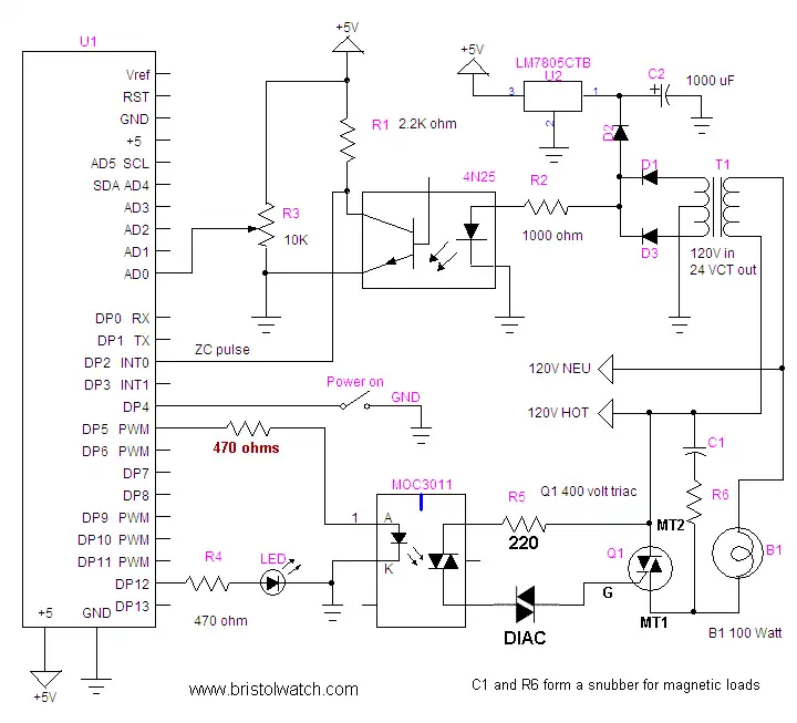
Basic schematic.
Arduino Hardware Interrupts Control AC Power
by Lewis Loflin
The purpose of this project is to demonstrate the use of a hardware interrupt to control AC power levels to a load such as a lamp or small AC motor. Note the "power on" switch must be pushed for the circuit to operate.
Warning: this circuit uses 120VAC and can cause injury if misused. Use under proper supervision and at your own risk.
See Warning About Electrical Shock and How to Prevent It
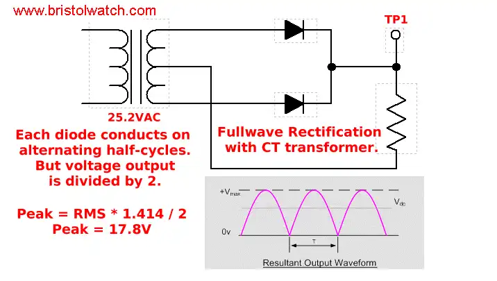
Full wave pulsating DC.
In the main circuit diagram above transformer T1, D1, and D3 produce a positive going pulsating DC with a peak voltage of about 18 volts and a frequency of 120 Hertz. Diode D2 blocks the filtering effect of capacitor C2, which with U2 supplies positive five volts for the microcontroller. See Basic AC Rectification and Filtering
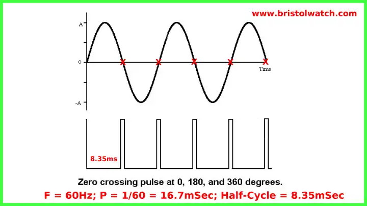
Zero crossing pulse from 4N25 in relation to AC sine wave.
The 4N25 opto-coupler provides a narrow 120 Hertz pulse at zero and 180 degrees of the sine wave. This pulse is fed to digital pin 2 (Dp2) of the controller to trigger an interrupt when the sine wave passes zero and 180 degrees. (There's 360 degrees in a sine wave.) See 4N25 Opto-Coupler (PDF file)
This illustrates to process with full-wave unfiltered D.C. but the process is identical with A.C.
By programming a delay of between .1 and 8.2 milliseconds (.1 and 9.9 on 50Hz systems) based on the voltage value on pin AD0 we control the firing point of a triac, transistor, or silicon controlled rectifier to control power output.
For this experiment one can use 24 volts A.C. and a 24 volt lamp. If the circuit is wired properly when the
control is adjusted the circuit should act as a lamp dimmer or speed control for a motor.
If the lamp dims as the control is adjusted clock-wise reverse the two outer connections on R3.
- Hardware Interrupts Tutorial for Arduino
- Basic Triacs and SCRs
- Solid State AC Relays with Triacs
- Light Activated Silicon Controlled Rectifier (LASCR)
- Arduino AC Power Control Using Interrupts
- In Depth Look at AC Power Control with Arduino
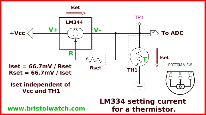
Sample circuit for photocell or thermistor
connection to ADC (analog to digital converter) sensor pin.
Uses
LM334 CCS Circuits with Thermistors, Photocells YouTube
LM334 CCS Circuits with Thermistors, Photocells
A circuit such as this can do far more than a $3 lamp dimmer. By connecting a thermistor to measure temperature (or an appropriate thermocouple circuit) to one of the analog inputs we have a proportional heat controller saving energy costs. We could control a heating element or the speed of a blower fan proportional to temperature.
By connecting a photocell we could control light intensity of lamps in proportion to natural light, saving energy costs with say sky lights. I use a version of this on my water heater to control a narrow temperature range.
In a proportional controller for heat as an example as the desired temperature is reached, power input is reduced automatically (delaying the firing point on the triac) and enough energy is added to maintain temperature. In a cheap mechanical thermostat power is all on or all off producing overshoot and undershoot. This is unacceptable in many industrial applications.
For an application of this circuit see Hatching Chicken Eggs with Arduino
See Controlling Low-Voltage Driveway Lights with the ATMEGA168/Arduino In that circuit we use a CdS photocell instead of a thermistor, but the circuit is identical.
Download Arduino code arduino_power_control.txt.
- Quick navigation of this website:
- Basic Electronics Learning and Projects
- Basic Solid State Component Projects
- Arduino Microcontroller Projects
- Raspberry Pi Electronics, Programming
Stepper Motors
- Easy Driver Micro-Stepper Controller to Arduino
- Unipolar Stepper Motor with a Arduino
- Considerations for Using Stepper Motors
- Connecting the Arduino to a L298N H-Bridge
- L298N Motor Controller Theory and Projects
- TA8050 H-Bridge Motor Controller
- Battery Charger related:
- Solar Panel Charge Controller Using Arduino
- Solar Panel Battery Charge Controller Using Arduino
- Solar Panel Battery Charge Controller Switching Circuit
- Arduino AC Power Control Tutorial
- Rotary Encoder Using Arduino Hardware Interrupts
- Arduino Controlling 74C164 Shift Register
- Arduino Interface MC3479 Stepper Motor Controller
Serial LCD Display and assorted Sensors
- Arduino LCD Display using 74164 Shift Register
- Arduino LCD Display with DS18B20
- Arduino LCD Display with DHT11 Sensor
- Arduino with MM5451 LED Display Driver
- Arduino MAX7219 Operates 8X8 LED Matrix
- Arduino RTC Clock MAX7219 LED Display
- BCD Conversion with MAX7219
- Hatching Chicken Eggs with Arduino
- Arduino TMP37 Temperature Sensor
- Arduino TMP37 Temperature Sensor Tutorial
- The following use obsolete parts and are kept as a reference.
- Testing the Keyes IR Sensor Module with Arduino
- Arduino to MCP23016, LCD Display
- Time-Date with Arduino, LCD Display, DS1307 RTC
- Controlling Driveway Lights with the Arduino
- TSL230R Light to Frequency Converter
- Arduino with MCP23016 I/O Expander
- Arduino DS1307 Real Time Clock
- Arduino with 24LC08 Serial EEPROM
- MC3479 Stepper Motor Controller with Arduino
Web site Copyright Lewis Loflin, All rights reserved.
If using this material on another site, please provide a link back to my site.