Arduino with Serially Interfaced MAX7219 Operates 8X8 LED Matrix
Related YouTube video for this project: Arduino DS1307 RTC Clock with MAX7219 LED Display Controller
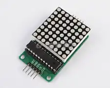
The following demonstrates the use of the MAX7219 display driver with a Arduino Microcontroller. This sample code move an arrow across a 8X8 LED matrix. These units are inexpensive and sold by several vendors on Ebay for under $5. This code was ported over from my PIC18F2550 pages and was designed to work on either micro-controller without the use of other user libraries. This makes the code more portable.
This demo operates in the non-decode mode.
The MAX7219 is a serial input/output common-cathode display driver that interfaces microprocessors to a 7-segment numeric LED displays of up to 8 digits, bar-graph displays, or 64 individual LEDs.
First the address (0x00 - 0x0f) is clocked in by ssrWrite(), then the data or command byte is clocked in.
Included on-chip are a BCD code-B decoder, multiplex scan circuitry, segment and digit drivers, and an 8x8 static RAM that stores each digit. Only one external resistor is required to set the segment current for all LEDs.
A convenient 4-wire serial interface connects to all common uPs. Individual digits may be addressed and updated without rewriting the entire display. The MAX7219 will also allow the user to select code- B decoding or no-decode for each digit.
The devices include a 150uA low-power shutdown mode, analog and digital brightness control, a scan limit register that allows the user to display from 1 to 8 digits, and a test mode that forces all LEDs on.
Arduino code for this project: arduino_max7219a.txt.
- Related:
- Arduino RTC Clock with MAX7219 8-Digit LED Display
- BCD Conversion with Arduino Displayed on MAX7219
- Raspberry Pi Python RTC Interface MAX7219 Display Driver
- Raspberry Pi Interfacing 8-Digit LED MAX7219 Display Driver
- Quick navigation of this website:
- Basic Electronics Learning and Projects
- Basic Solid State Component Projects
- Arduino Microcontroller Projects
- Raspberry Pi Electronics, Programming
Stepper Motors
- Easy Driver Micro-Stepper Controller to Arduino
- Unipolar Stepper Motor with a Arduino
- Considerations for Using Stepper Motors
- Connecting the Arduino to a L298N H-Bridge
- L298N Motor Controller Theory and Projects
- TA8050 H-Bridge Motor Controller
- Battery Charger related:
- Solar Panel Charge Controller Using Arduino
- Solar Panel Battery Charge Controller Using Arduino
- Solar Panel Battery Charge Controller Switching Circuit
- Arduino AC Power Control Tutorial
- Rotary Encoder Using Arduino Hardware Interrupts
- Arduino Controlling 74C164 Shift Register
- Arduino Interface MC3479 Stepper Motor Controller
Serial LCD Display and assorted Sensors
- Arduino LCD Display using 74164 Shift Register
- Arduino LCD Display with DS18B20
- Arduino LCD Display with DHT11 Sensor
- Arduino with MM5451 LED Display Driver
- Arduino MAX7219 Operates 8X8 LED Matrix
- Arduino RTC Clock MAX7219 LED Display
- BCD Conversion with MAX7219
- Hatching Chicken Eggs with Arduino
- Arduino TMP37 Temperature Sensor
- Arduino TMP37 Temperature Sensor Tutorial
- Testing the Keyes IR Sensor Module with Arduino
- Arduino to MCP23016, LCD Display
- Time-Date with Arduino, LCD Display, DS1307 RTC
- Controlling Driveway Lights with the Arduino
- TSL230R Light to Frequency Converter
- Arduino with MCP23016 I/O Expander
- Arduino DS1307 Real Time Clock
- Arduino with 24LC08 Serial EEPROM
- MC3479 Stepper Motor Controller with Arduino
Web site Copyright Lewis Loflin, All rights reserved.
If using this material on another site, please provide a link back to my site.