PIC18F2550 PIC Controller Interface MAX7219 Display Controller
YouTube video: MAX7219 display controller with 8X8 LED Matrix
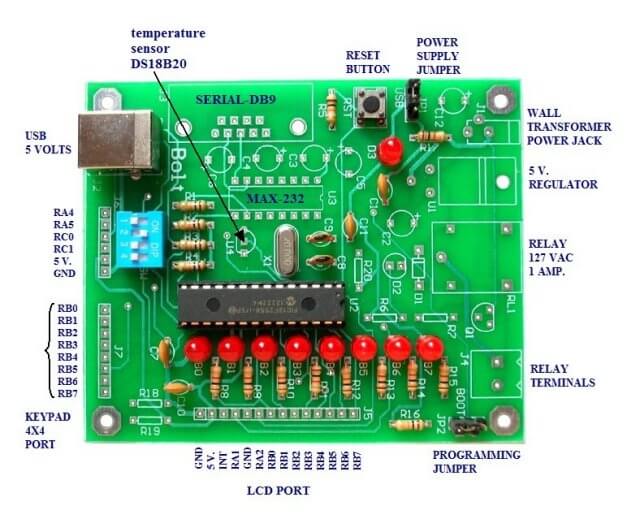
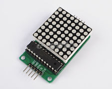
Once again we are using the MAX7219 display controller with the with the BOLT 18F2550 micro controller board. We won't use the built in BCD decode function and will place a moving pattern on a 8X8 LED matrix.
We change only one line in the init_MAX7219() subroutine:
// set decode mode
	ssrOut(0x09); // address
	// ssrOut(0x00); // no decode
	ssrOut(0xFF); // 4-bit BCD decode eight digits
	pulseCS();
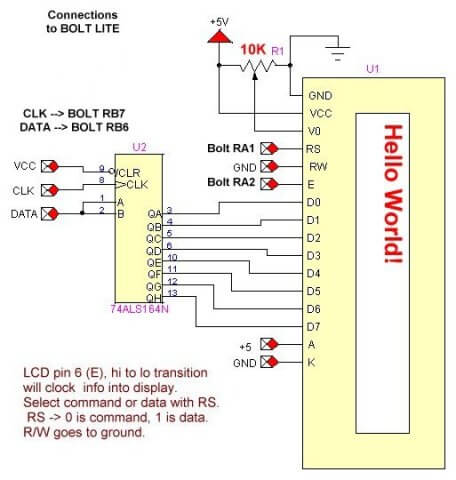
Simply uncomment line 2 and comment line three. the pattern is stored in array1[] and the other routines are the same. See the schematics and other associated information below for more on the electronics.
The speed of the arrow across the matrix is controlled by reading a potentiometer connected RA5 on the 18F2550.
- Related added Nov. 15, 2013:
- Arduino with Serially Interfaced MAX7219 Operates 8X8 LED Matrix
- Arduino RTC Clock with MAX7219 8-Digit LED Display
- BCD Conversion with Arduino Displayed on MAX7219
#include <p18cxxx.h>
#include <delays.h>

#define HIGH 1
#define LOW 0

#define RB5  PORTBbits.RB5  // CS
#define RB6  PORTBbits.RB6  // DATA
#define RB7  PORTBbits.RB7  // CLK
#define delay_us	Delay10TCYx

// function declarations
void ssrOut(unsigned char);
void pulseCS(void);
void init_MAX7219(void);
void writeMAX7219(char, char);
// ADC functions
void open_adc(void);
int read_adc(void);
void init_PIC18F2550(void);
void delay_ms(int);

extern void _startup( void );
// See c018i.c in your C18 compiler dir
#pragma code _RESET_INTERRUPT_VECTOR = 0x000800
void _reset( void )
{
  _asm goto _startup _endasm
}

#pragma code

int i, j, k;


// pattern for 8 X 8 LED matrix
char array1[] = {
  0x00, 0x00, 0x81, 0x42, 0x24, 0x18,
0x00, 0x00, 0x00, 0x00, 0x00 };

void main()
{
  //user program
  init_PIC18F2550();
  init_MAX7219(); // 8 char decode off
  open_adc();
  k = 0;
loop:
  for (j=1; j<9; j++)   {
    writeMAX7219(j+k, array1[j]);
  }
  i = read_adc(); // read pot connected to RA5
  if (i<10) i = 10;
  delay_ms(i);
  k++;
  if (k > 8) k = 0;
  goto loop;

} //end main

// shift data to MAX7219
// RB7 -> CLK, RB6 -> DATA, RB5 -> CS not
void ssrOut(unsigned char val)  {
  int j;
  for(j=1; j<=8; j++)  {   // shift out MSB first
    unsigned char  temp = val & 0x80; // MSB out first
    if (temp == 0x80) RB6 = HIGH; // RB6 DATA
    else RB6 = LOW;
    RB7 = HIGH;
    delay_us(20);
    RB7 = LOW;
    val = val << 1; // shift one place left
  }  // next j
}


void pulseCS(void)   {
  RB5 = HIGH;
  delay_ms(1);
  RB5 = LOW;
}


void init_MAX7219(void)   {
  RB5 = LOW; // CS NOT

  // set decode mode
  ssrOut(0x09); // address
  // ssrOut(0x00); // no decode
  ssrOut(0xFF);
  // 4-bit BCD decode eight digits
  pulseCS();

  // set intensity
  ssrOut(0x0A);
  ssrOut(0x0D); // 0 - F
  pulseCS();

  // set scan limit
  ssrOut(0x0B);
  ssrOut(0x07); // 8 digits
  pulseCS();

  // clear MAX7219
  for(i=1; i<=8; i++)   {
    ssrOut(i);
    ssrOut(0x00);
    pulseCS();
  }

  // set for normal operation
  ssrOut(0x0C);
  ssrOut(0x01);
  pulseCS();

}


void writeMAX7219(char address, char data)   {
  if ((address < 1) || (address > 8)) return;
  ssrOut(address); // valid numbers 1-8
  ssrOut(data);
  pulseCS();
}


// The analog input channels must have their
// corresponding TRIS bits selected as an input.
void open_adc(void)   { //INITIALIZE CHANNEL 4
  ADCON0 = 0x11;     // set for CH4, Bit 0 ADON = 1
  ADCON1 = 0x3F;   // all digital just for setup
  ADCON2 = 0xAE;	// see page 257 spec sheet
  // disable interrupt
  PIR1bits.ADIF = HIGH;
  PIE1bits.ADIE = LOW;
}

int read_adc(void)   {
  //RETURNS WITH RESULT OF ADC
  // on BOLT ADCON1bits.VCFG0 = 1; VREF+ (AN3) and not VCC
  int val;
  ADCON1=10;
  // ADCON1bits.ADON = 0 turn off for read
  ADCON0bits.GO = 1;
  // initiate conversion
  while( ADCON0bits.GO );
  // wait for LOW - end of conversion
  val = (ADRESH * 256) + ADRESL;
  // reads/calculates result
  ADCON1=15;	//CHANNEL 4 off
  return val;
}


//Ports initialised A, B, C
void init_PIC18F2550(void)   {
  ADCON1=0x0F; // disables converters A/D
  CMCON=7;
  TRISB=0; //PORTB are outputs
  PORTB=0; // off LEDS
  TRISA=0X30;
  //RA4,RA5 are inputs. RA0,RA1,RA2,RA3 outputs
  TRISC=0X0F; 	//RC0,RC1 are inputs (MICROSWITCHES)
  INTCON2bits.RBPU=0;
  //pull-up resistors on port B (RB4...RB7).
}

void delay_ms(int i)
{
  long int j;
  for(j=0;j<i;j++)
  {
    Delay1KTCYx(12); 	//48 MHZ, DELAY OF 1 MS APROX.
  }
}
See How I got into Electronics
Videos, Links, Downloads for the PIC18F2550 BOLT
- Introducing the BOLT PIC18F2550 Microcontroller Board
- PIC18F2550 BOLT with Serial LCD Display
- Using the MAX7219 with the 18F2550 Programs:
- MAX7219 Display Driver and a PIC Micro Controller
- MAX7219 Display Controller in the Non-Decode Mode with PIC
- Using TMR0 and Interrupts on the PIC18F2550
- YouTube Videos:
- My YouTube Channel
- MAX7219 display controller with 8X8 LED Matrix
- Programming the MAX7219 and 7-Segment Display
- Connecting PIC18F2550 to Parallel LCD Display
- Connecting PIC18F2550 to Serial LCD Displays
- Downloads:
- lewislcd.h My LCD H file
- Schematic Serial LCD
- BOLT_Template.zip
- Bolt Getting Started (pdf)

- Assembly language projects using PIC16F628:
- Exploring the Microchip PIC in Assembly
- Using a Microchip PIC with TLC548 Serial ADC
- Controlling PIC Pulse Width Modulation with a Serial ADC
- Using TMR0 on a PIC with Interrupts
- External Clock Crystal with PIC16F628 TMR1 Generates Interrupt
- PIC Using Rotary Encoder to Operate Stepper Motor
- PIC16F628 Pulse Width Modulation Controls Brightness of LED
- Another way to Turn On-Off PWM in a PIC
- TLC548 Serial ADC Spec. Sheet
Web site Copyright Lewis Loflin, All rights reserved.
If using this material on another site, please provide a link back to my site.