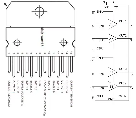
Basic Pin Connection on the L298N Dual H-Bridge
Stepper Motor Control Basics with Arduino
Schematics to the following stepper motor video:
The Arduino sketch below replaces the Stepper library which I found useless. It also includes I2C display as shown in the video. I consist of the command forward(int steps, int step_delay) and reverse(int steps, int step_delay). It also a motor off command.
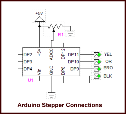
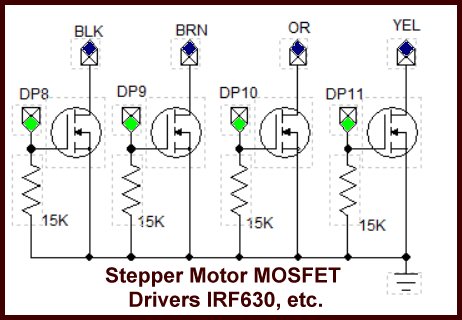
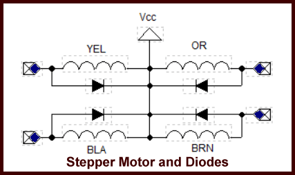
A potentiometer is connected to ADC0 can be used to control the step delay. On my particular stepper motor a step delay less than 5 mSec. will stall the motor. The motor is 1.8 degrees per step or 200 steps for 360 degrees rotation. Each winding is 5.1 volts at 1 amp. The color code is based on a motor from an earlier program. Have fun.
Download Arduino code stepper.txt copy and paste to Arduino compiler.
From a visitor:
I am building a 3D printer using unipolar stepper motor 57BYG084, it is a 4 phase, 6 wires stepper. I have an Arduino Mega 2560 with RAMPS 1.4 and A4988 stepper driver. According to Pololu website, it said A4988 can drive unipolar stepper. Yes, it can but runs really slow, the top speed is about 59 IPM or 1500mm/min.
The same motor is running fine with MAXNC stepper driver, roughly 200 IPM. MAXNC stepper driver has the same TIP120 Darlington power transistor as in your EasyDriver V4.4. To me, both A4988 and A3967 are designed to do the same for bipolar stepper. Is it possible just adding the power transistor TIP120 to A4988 to drive 57BYG084?

The 57BYG084 is a 12 V DC 600 mA per winding motor. This can be operated in the bipolar mode by leaving the center taps of the two coils disconnected. But one will also have to double the coil voltage to 24 V.
Now we're dealing with several issues here I'll address them one at a time.
The issue of 24 V addresses torque and not speed very much. When we connect these two 12-volt coils in series one must also note that we have doubled the inductive reactance. The fact that this motor is operating at 12 V tells me it has a fair amount of inductive reactance (25 mH). Connecting these two coils essentially in series by leaving the center tap floating doubles that to 50mH.
Thus this plays into the issue of the time delay between steps as we will see below. Higher inductive reactance means a slower motor because I have more time between steps.
The A4988 data sheet shows that this device will produce 1/16 steps. Now let's put this in perspective: your particular stepper motor is 1.8 degrees per step or 200 steps for 360 degrees. If the A4988 is set at 1/16 step it will take 3200 steps to turn the stepper motor shaft 360 degrees. Now compound this by saying a threaded rod of 20 turns per inch times 3200 equals 64,000 steps per inch.
Now these numbers are starting to get a little astronomical. How fast in RPMs a stepper motor will turn is a product of steps times delay between steps. Stepper motors are still electromechanical devices thus the electronics can operate at a far higher speed than the motor could ever achieve.
So between every step there has to be a time delay. So if we have a time delay between steps of say 5 ms times 64,000 just to move one-inch equals 320 seconds or 5.33 minutes. Get my point?
So now we have a few choices to make. We can shorten the delay between steps but this is going to play havoc with possible inductive reactance problems, load, and torque. The best choice would be to change the degrees per step.
So let's go with quarter steps. 200 times four equals 800 steps per revolution times 20 revolutions per inch equals 16,000 steps per inch. 16,000 times 5 ms equals 80 seconds 0r 1 minute 20 sec.
At this point we have speeded up the motor but this is at the cost of a little accuracy. Perhaps we want more steps, but perhaps a shorter time delay. If we get half the time delay we could use 1/8 steps for better accuracy in the same time period.
Now were back to the problem we initially faced in that the higher inductive reactance of the motor combined with the fact we are using the windings in series won't let us reduce the delay.
So this is what I think you're going to have to do: connect your motor as a unipolar as in my video and schematic. You need to make sure what step mode the controller is set for.
It may take a little experimentation to get the windings connected correctly. If the motor misses or runs rough reverse the winding pairs until proper operation. The advantage of operating as a bipolar motor is direction can be reversed simply by swapping the wire pairs. That doesn't apply in unipolar mode.
The issue of IPM is addressed further down.
Good luck.

From: http://probotix.com/stepper_motor_calculations/
IPM = (Frequency * 60) / (Turns Per Inch * Steps Per Revolution * Microsteps)
Configuring software steps per unit:
This variable stores how many steps to take to move the X axis 1 inch. You will need to set this as accurately as possible if you want your machine to be accurate. There are two ways to set it:
Move and Measure - slap a pen or marker on as a tool head and draw a 1000 step line. Measure it and divide 1000 by the length in inches. Calculate Step Size - this one is the preferred way of doing things. Its rather easy to calculate step size based on your drive mechanism.
For threaded rod type drive systems:
Find your TPI (Turns Per Inch). for example, 1/4"-20 threaded rod means that there are 20 threads per inch single start (aka 20 turns = 1 inch.) Simply take that number and multiply it by the steps in a revolution. With a 400 step motor (200 steps per revolution at half step), it would be 8000 steps per inch.
For belt/pulley systems:
Find the circumference of your drive pulley. (remember circumference = 2*pi*r) (say: 2.75") Calculate step size (ie: circumference / steps per revolution) (say: 2.75" / 400 = 0.00625") Divide 1 inch by step size (1" / 0.00625" = 160 steps/inch)
- Opto-Isolated transistor driver circuits.
- Transistor Driver Circuits
- Opto-Isolated Transistor Drivers
- Optical Isolation of H-Bridge Motor Controls
- MOSFET Transistors, IGBTs Observations
- Example H-Bridge Circuits
- L298N Motor Controller Theory and Projects
- Connecting the Arduino to a L298N H-Bridge
- All NPN Transistor H-Bridge Motor Control
- IGBT Based High Voltage H-Bridge DC Motor Control
- Arduino Controlled IR2110 Based H-Bridge HV Motor Control
- Tri-State H-Bridge using CD4093B CMOS Circuit
- CMOS-MOSFET H-Bridge Circuit
- Interfacing Arduino to CMOS and MOSFET Circuits
- Transistor circuits:
- ULN2003A Darlington Transistor Array with Circuit Examples
- Tutorial Using TIP120 and TIP125 Power Darlington Transistors
- Driving 2N3055-MJ2955 Power Transistors
- Understanding Bipolar Transistor Switches
- N-Channel Power MOSFET Switching Tutorial
- P-Channel Power MOSFET Switch Tutorial
- More Power MOSFET H-Bridge Circuit Examples
- Build a High Power Transistor H-Bridge Motor Control
- MOSFET-Transistor Drivers with TC4420 and TC4429, IGBTs, etc.
- Introduction TC4420-TC4429 MOSFET Drivers
- Use TC4420 MOSFET Driver for Simple H-Bridge Circuit
- TC4420 MOSFET Driver Various Circuits
- TC4420 MOSFET Driver Replacement Circuits
- Test Power MOSFET Transistors, IGBTs
- Insulated Gate Bipolar Transistor IGBT Circuits
- Issues on Connecting MOSFETs in Parallel
Stepper Motors
- Easy Driver Micro-Stepper Controller to Arduino
- Unipolar Stepper Motor with a Arduino
- MC3479 Stepper Motor Controller with Arduino
- Considerations for Using Stepper Motors
- Connecting the Arduino to a L298N H-Bridge
- L298N Motor Controller Theory and Projects
- TA8050 H-Bridge Motor Controller
- Arduino Stepper Motor Coil Winder
- Using Hall Effect Switches and Sensors
- ULN2003A Darlington Transistor Array with Circuit Examples
- Tutorial Using TIP120 and TIP125 Power Darlington Transistors
- H-Bridge Motor Control with Power MOSFETs
- More Power MOSFET H-Bridge Circuit Examples
- Build a High Power Transistor H-Bridge Motor Control
Web site Copyright Lewis Loflin, All rights reserved.
If using this material on another site, please provide a link back to my site.