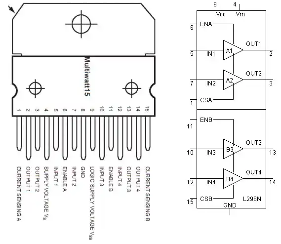
Basic Pin Connection on the L298N Dual H-Bridge
L298N Motor Controller Theory Projects
In this series we will explore how to use the L298N in a number of actual tested and functioning circuits. The part is inexpensive costing under $2 on Ebay. It can source/sink up to four amps at about 40 volts with proper heat sinking.
As shown in the above illustrations I have redrawn the "multi-watt" package into a more understandable form. Internally the L298N consists of four independent power amps with 5-volt digital inputs and four high current, high voltage power amplifiers capable of driving single DC motors, and both unipolar and bi-polar stepper motors.
The four amplifiers are usually used in pairs forming an H-bridge to switch polarity for to control the direction of a single DC motor or as two pairs of H-bridges a bi-polar stepper motor. This part seems to be the favorite of hobby robot builders.
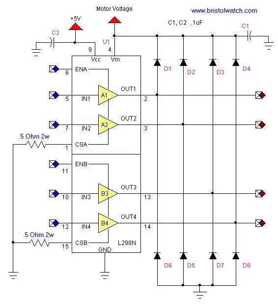
Basic circuit configuration L298N
More Detailed Explanation
Pictured above is the basic L298N circuit used to drive inductive/magnetic loads. One of the annoying features of the unit is the lack of internal parasitic (flywheel) diodes to deal with voltage spikes. D1 - D8 are used for this purpose. They can be 1N5819 Schottky diodes. I have used more common 1N4001 rectifier diodes and they seem to work fine. Perhaps an updated version will include these internally.
The four power amplifiers and grouped in pairs of two with individual enable pins (ENA, ENB) and individual current sense pins (CSA, CSB) for each pair. The current sense pins in general can be tied to ground, but one can insert low value resistor, whose voltage reading is proportional to current.
ENA, ENB, and In1-In4 are all standard 5-volt TTL logic making connection to most micro-controllers easy. ENA will turn on A1 and A2 when with a digital HIGH (5-volts) and off when LOW (0 volts); the corresponding outputs will be floating when off. Same is true of ENB, In3 and In4. ENA and ENB can be connected directly together to enable both channels at once or simply tied to +5 volts and both channels making all four outputs active at all times.
A 5-volt TTL level input to In1, In2 In3, or In4 will produce a corresponding output of Vm (motor voltage) minus about a volt.
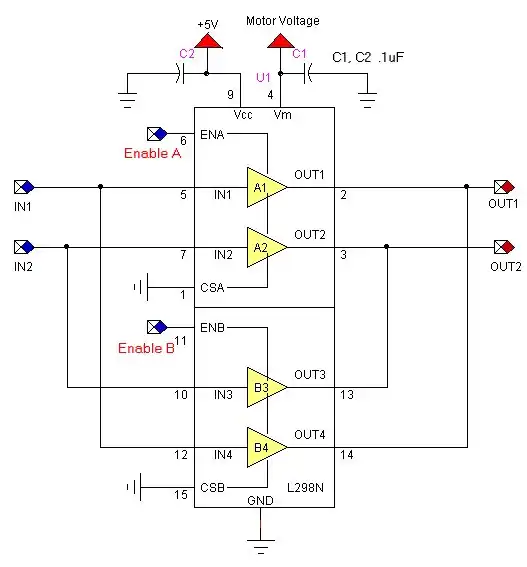
Figure 3
Shown in figure 3 the power amps have connected in parallel for double the power at the cost of operating one bi-directional load such as a DC motor. The two enable pins should be tied together. Take care to parallel channel1 with channel 4 and channel 2 with channel 3.
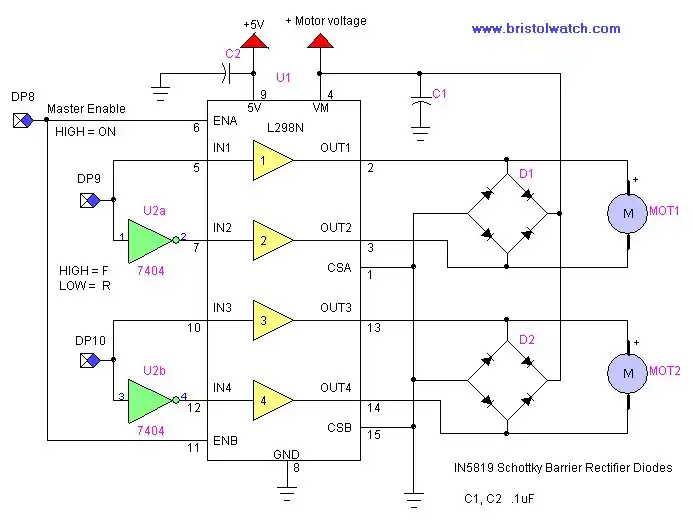
Figure 5.
Figure 5 shows the L298N being used with a 74LS04 HEX inverter to allow only three digital pins to control two separate DC motors. In this case the circuit can be used in a X-Y axis setup such as one finds on a small CNC machine. While wired together here, the two enable pins can be separated to turn each individual motor on/off separately.

Figure 6
Shown above is a pre-assembled board I bought off Ebay for $8 with shipping. This included power connectors, diodes, LED indicators, and even a 5-volt regulator. This is in my opinion the smart way to go to save time, money, and effort.
This completes our introduction to the L298N dual full bridge driver. In the proceeding sections we will connect the L298N to a micro-controller to operate a bi-polar stepper motor and explore using pulse-width-modulation (PWM) to control motor speed on a standard DC motor.
- H-Bridge Motor Control with Power MOSFETS Updated
- All NPN Transistor H-Bridge Motor Control
- IGBT Based High Voltage H-Bridge DC Motor Control
- Arduino Controlled IR2110 Based H-Bridge HV Motor Control
- Tri-State H-Bridge using CD4093B CMOS Circuit
- CMOS-MOSFET H-Bridge Circuit
- Interfacing Arduino to CMOS and MOSFET Circuits
- Quick navigation of this website:
- Basic Electronics Learning and Projects
- Basic Solid State Component Projects
- Arduino Microcontroller Projects
- Raspberry Pi Electronics, Programming
- Opto-Isolated transistor driver circuits.
- Transistor Driver Circuits
- Opto-Isolated Transistor Drivers
- Optical Isolation of H-Bridge Motor Controls
- MOSFET Transistors, IGBTs Observations
- Example H-Bridge Circuits
- L298N Motor Controller Theory and Projects
- Connecting the Arduino to a L298N H-Bridge
- All NPN Transistor H-Bridge Motor Control
- IGBT Based High Voltage H-Bridge DC Motor Control
- Arduino Controlled IR2110 Based H-Bridge HV Motor Control
- Tri-State H-Bridge using CD4093B CMOS Circuit
- CMOS-MOSFET H-Bridge Circuit
- Interfacing Arduino to CMOS and MOSFET Circuits
- Transistor circuits:
- ULN2003A Darlington Transistor Array with Circuit Examples
- Tutorial Using TIP120 and TIP125 Power Darlington Transistors
- Driving 2N3055-MJ2955 Power Transistors
- Understanding Bipolar Transistor Switches
- N-Channel Power MOSFET Switching Tutorial
- P-Channel Power MOSFET Switch Tutorial
- More Power MOSFET H-Bridge Circuit Examples
- Build a High Power Transistor H-Bridge Motor Control
- MOSFET-Transistor Drivers with TC4420 and TC4429, IGBTs, etc.
- Introduction TC4420-TC4429 MOSFET Drivers
- Use TC4420 MOSFET Driver for Simple H-Bridge Circuit
- TC4420 MOSFET Driver Various Circuits
- TC4420 MOSFET Driver Replacement Circuits
- Test Power MOSFET Transistors, IGBTs
- Insulated Gate Bipolar Transistor IGBT Circuits
- Issues on Connecting MOSFETs in Parallel
Stepper Motors
- Easy Driver Micro-Stepper Controller to Arduino
- Unipolar Stepper Motor with a Arduino
- MC3479 Stepper Motor Controller with Arduino
- Considerations for Using Stepper Motors
- Connecting the Arduino to a L298N H-Bridge
- L298N Motor Controller Theory and Projects
- TA8050 H-Bridge Motor Controller
- Using Hall Effect Switches and Sensors
- ULN2003A Darlington Transistor Array with Circuit Examples
- Tutorial Using TIP120 and TIP125 Power Darlington Transistors
- H-Bridge Motor Control with Power MOSFETs
- More Power MOSFET H-Bridge Circuit Examples
- Build a High Power Transistor H-Bridge Motor Control
Web site Copyright Lewis Loflin, All rights reserved.
If using this material on another site, please provide a link back to my site.