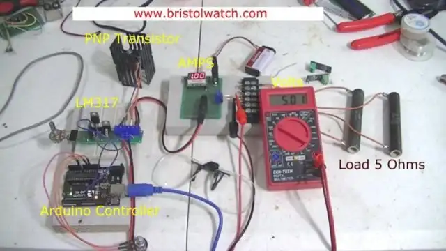
Fig. 1 Test setup Arduino controlled constant current source.
Arduino Controlled Constant Current Source
by Lewis Loflin
Note: click on any image for larger view.
Adding a single switching transistor enables microcontroller control of the output. Current limit can also be set.
For more on the original constant current source see Constant Current Source Theory Testing.
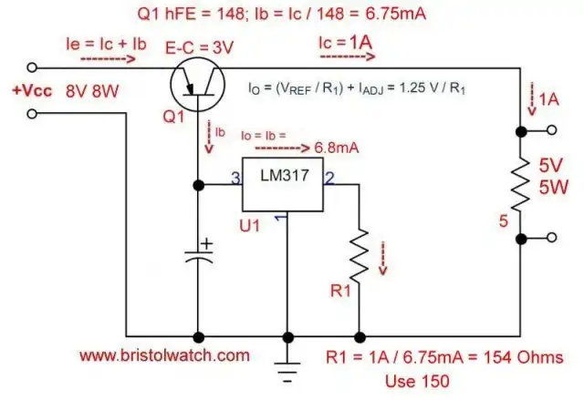
Fig. 2 LM317 controls MJ2955 transistor creating a 1-amp constant current source.
The original CCS circuit is shown in Fig. 2. The LM317 circuit sets the emitter-base current. This controls the emitter-collector current through Q1.

Fig. 3 LM317 CCS with transistor ON/OFF switch for PWM, etc.
By adding a TIP120 transistor to the ground circuit allows an Arduino to switch the current ON-OFF. This also enables the use of pulse-width-modulation to control the output.
Iset now determines maximum current while Arduino or other microcontroller controls overall power output by varying the duty cycle - or full on.
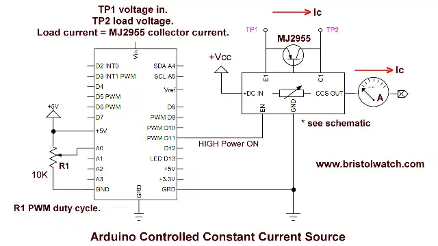
Fig. 4 Wiring diagram Arduino controlled constant current source.
Click for larger image.
Fig. 4 is the circuit used in the demo video.
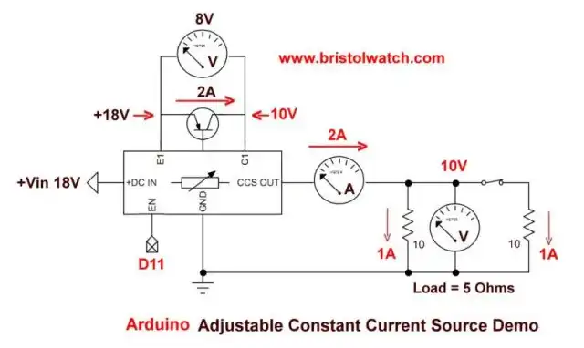
Fig. 5 Electrical test schematic Arduino controlled variable constant current source.
Fig. 5 are the load connections in the test circuit.
Code
#define pwmPin 11

int val;
void setup() {
  // put your setup code here, to run once:
  digitalWrite(pwmPin, 0);
}

void loop() {
  // put your main code here, to run repeatedly:
  val = analogRead(0) / 4;
  analogWrite(pwmPin, val);
  delay(100);
}
![]()
- Quick navigation of this website:
- You Tube Channel
- Basic Electronics Learning and Projects
- Homepage Lewis Loflin
- Follow on X
- Skeptic Site
- Religion 1
- Religion 2
- Coils for Highly Selective Crystal Radio
- Neon (NE-2) Circuits You Can Build
- Understanding Xenon Flashtubes and Circuits
- Hall Effect Magnetic Switches and Sensors
- Transistor-Zener Diode Regulator Circuits
- Build an Adjustable 0-34 volt power supply with the LM317
- Simple 2 Transistor LED Flasher Circuit
- LM2575 Simple Switching Voltage Regulators
- LM317 Constant Current Source for Lighting LEDs
- IGBT Based High Voltage H-Bridge DC Motor Control
- Arduino Controlled IR2110 Based H-Bridge HV Motor Control
- Understanding Unijunction Transistors Theory Operation
- Arduino Measures Current from Constant Current Source
- Constant Current Source Theory Testing
- Review Ohm's Law for Trouble-Shooting CCS Circuits
- Arduino Power Magnetic Driver Board for Stepper Motors
- Arduino Controlled Power Constant Current Source
- Theory and Operation of Capacitors
Related video to above:
- Measure Current from Constant Current Source with Arduino
- Constant Current Source Multimeter Trouble Shooting
- Ohm's Law Review for Constant Current Source
- Arduino Unipolar Stepper Motor Driver Board with Arduino Code
- Arduino Controlled Constant Current Source
- LM317 Adjustable Current Boost Power Supply
- Constant Current Circuits LM334, LM317
- Build LM317 0-34 Volt Power Supply
- LM334 Constant Current Source with Resistive Sensors
- LM317 High Power Constant Current Source Circuit
- LM317 Constant Current Source Circuits
- Test SCRs and Triacs
- Basic MOSFET Transistor Test Circuits
- High Voltage MOSFET Switching Circuits
- 3 Amp LM741 Op-Amp Constant Current Source
- Current Limiter Testing of Zener Diodes
- Current Limiter for Opto-Coupler Inputs
- LM317 CCS for Light Emitting Diodes
Web site Copyright Lewis Loflin, All rights reserved.
If using this material on another site, please provide a link back to my site.