Fig. 1
Optocoupler Input Circuits for PLCs
by Lewis Loflin
Here I'll introduce programmable logic controller (PLC) input circuits using opto-couplers. We use these devices to interface high voltage sensors to low voltage microcontroller logic and to isolate sensitive circuits from noise.
I'll also discuss the concepts of SOURCE and SINK.
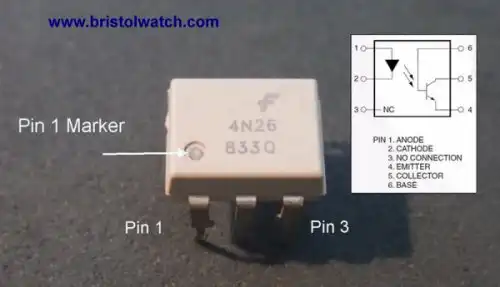
Fig. 1 illustrates a typical 6-pin opto-coupler. These can also be surface mount as well. All contain an LED emitter and many a photo transistor output.
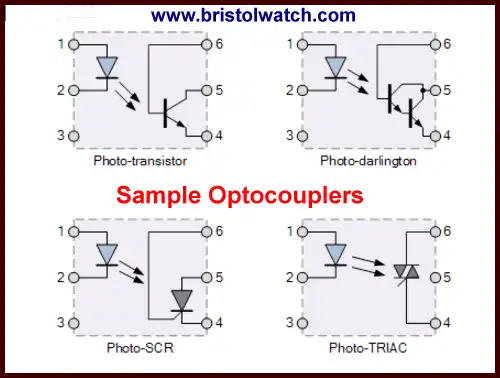
Fig. 2
Fig. 2 show just a few of the many types of optocouplers. The bottom two are often used as output while the top two can be either way.
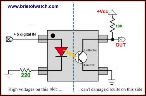
Fig. 3
Fig 3 illustrates a typical bipolar transistor opto-coupler to a microcontroller.
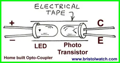
Fig. 4
Fig 4 shows how to build you own opto-coupler with a light emitting diode and a photo transistor.
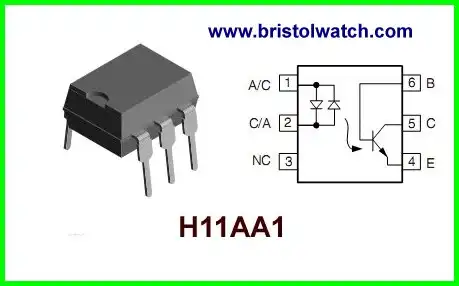
Fig. 5
The H11AA1 is a very useful device because the dual back-to-back LEDs simplify circuits design because we don't have to worry about input polarity.
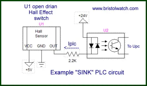
Fig. 6
Fig. 6 shows what is called a SINK configuration. This refers to the current path in relation to the PLC input. (This is really simplified.)
U1 is an open drain or collector in this case a Hall effect sensor. When a magnet turns on the Hall sensor a path to ground is enabled through the output pin. When U1 is turned on one of the LEDs is turned on switching on the transistor. The 5-volt micro-controller reads this as a switch closure.
The switching is in the ground side of the PLC input.
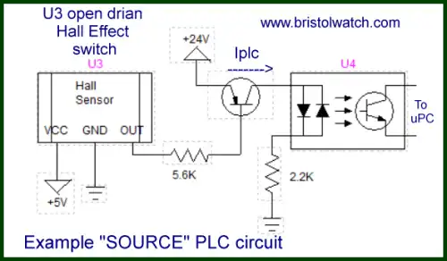
Fig. 7
Fig. 7 illustrates a SOURCE configuration. When U3 is turned on it switching on a PNP transistor completing the current path though the H11AA1 to ground. The switching is on the positive supply side of the PLC input.
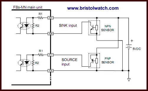
Fig. 8
Fig 8 shows both SINK and SOURCE inputs on the same PLC. Because the opto-coupler is say a 4N26 with a single LED we must observe LED polarity.
In Fig. 6 the NPN transistor was internal to the Hall sensor.
- Quick navigation of this website:
- Basic Electronics Learning and Projects
- Basic Solid State Component Projects
- Arduino Microcontroller Projects
- Raspberry Pi Electronics, Programming
- Comparator Theory Circuits Tutorial
- Zero-Crossing Detectors Circuits and Applications
- Improved AC Zero Crossing Detectors for Arduino
- Photodiode Circuits Operation and Uses
- Photodiode Op-Amp Circuits Tutorial
- Issues on Connecting MOSFETs in Parallel
- MOSFET DC Relays Using Photovoltaic drivers
- Optocoupler Input Circuits for PLC
- All NPN Transistor H-Bridge Motor Control
- Photo Voltaic Tutorial MOSFET Output Solid State Relays
- Optical Isolation of H-Bridge Motor Controls
- Design 10-Amp 2N3055 Based Power Switch
- TA8050P H-Bridge Motor Control
- Connecting Crydom MOSFET Solid State Relays
- H11L1, 6N137A, FED8183, TLP2662 Digital Output Optocouplers
- Arduino
- Arduino PWM to Analog Conversion
- Arduino Analog Digital Conversion Voltmeter
- Better Arduino Rotary Encoder Sensor
- Simple 3-Wire MAX6675 Thermocouple ADC Arduino Interface
- Hall Effect Magnetic Switches and Sensors
- Transistor-Zener Diode Regulator Circuits
- Build an Adjustable 0-34 volt power supply with the LM317
- Coils for Highly Selective Crystal Radio
- Neon (NE-2) Circuits You Can Build
- Understanding Xenon Flashtubes and Circuits
- LM2575 Simple Switching Voltage Regulators
- Simple 2 Transistor LED Flasher Circuit
- Generating High Voltage with an Inductor
Web site Copyright Lewis Loflin, All rights reserved.
If using this material on another site, please provide a link back to my site.