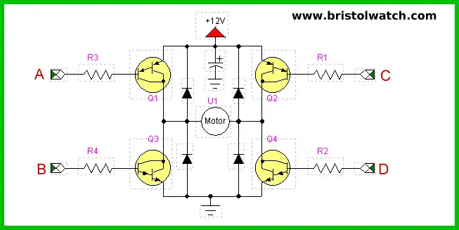
Fig. 1 Basic transistor H-bridge circuit.
NPN Only Transistor H-Bridge Circuits
by Lewis Loflin
Here we look at construction of all NPN transistor h-bridge circuits. This is being done to learn further transistor theory and to deal with the problem of hard to find and often expensive PNP power transistors.
Fig. 1 shows an example h-bridge circuit using bipolar transistors. Note that if one is using transistors without internal diodes for absorbing counter-electromotive force they will have to be supplied externally.
My examples that follow will use NPN Darlington transistors such as the TIP120 with built in diodes and we work on the assumption the circuit will be controlled by a standard 5-volt micro-controller such as Arduino or PIC.
If one really requires a very large drive current say over 4 amps, then consider using 2N3055s with say a TIP31 in a Darlington pre-driver configuration. For background on these issues see:
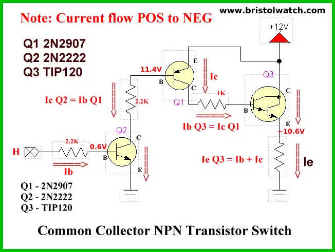
Fig. 2
Here in fig. 2 we have replaced the PNP transistors Q1 and Q2 in Fig. 1 (one of these circuits for each transistor) with a power NPN transistor Q3 and two driver transistors Q1 and Q2. Q1 acts as a switch to supply base current (Ib) to Q3 switching it on. Q2 is used to switch on Q1 and to protect the 5-volt Arduino I/O from the high voltage on the base of Q1.
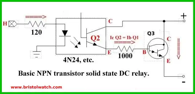
Fig. 3
In Fig. 3 we have replaced Q1 and Q2 with a single 4N25 opto-coupler whose photo transistor Q2 switches on to supply base current for Q3. The 4N25 provide voltage isolation between the micro-controller and 12-volt motor power supply.
See Opto-Isolated Transistor Drivers for Micro-Controllers
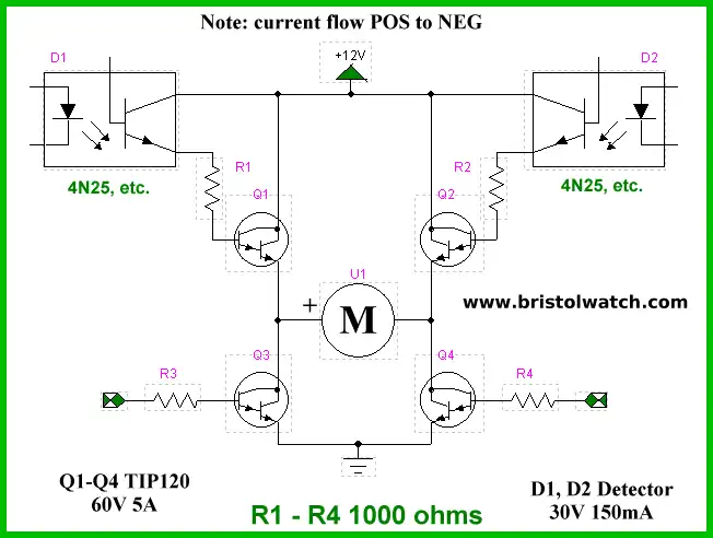
Fig. 4
Here we have redrawn the circuit using all the same NPN power transistors with opto-couplers for Q1 and Q2. The circuit in Fig. 2 works just as well. All 4 inputs are a direct 5-volt TTL connection.
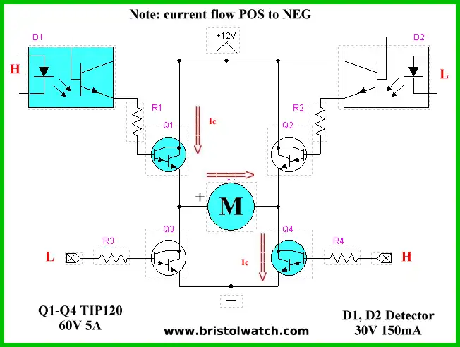
Fig. 5
In Fig. 5 we switch on D1 which switches on Q1 and we also switch on Q4 creating a current path for the motor to run clock-wise.
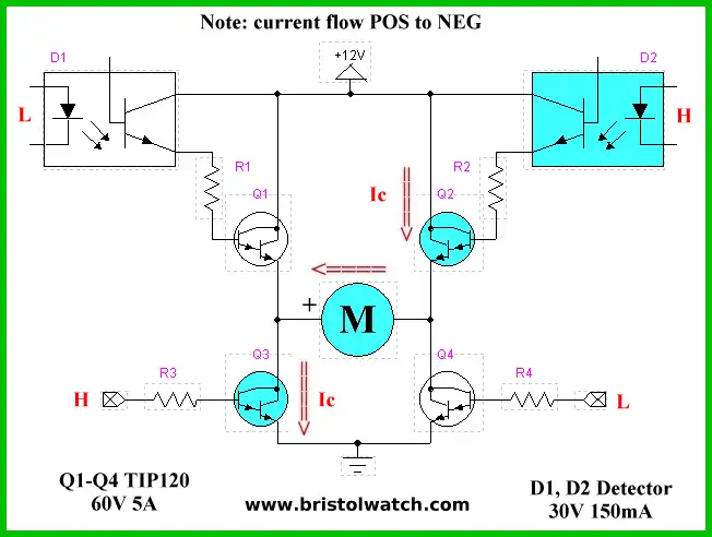
Fig. 6
In Fig. 6 we switch on D2, Q2, and Q3 creating an opposite current path for the motor now running counter-clockwise.
This completes our brief introduction to NPN transistor h-bridge circuits.
- Tutorial Using TIP120 and TIP125 Power Darlington Transistors
- Driving 2N3055-MJ2955 Power Transistors
- Understanding Bipolar Transistor Switches
- Build a High Power Transistor H-Bridge Motor Control
- Quick navigation of this website:
- Basic Electronics Learning and Projects
- Basic Solid State Component Projects
- Arduino Microcontroller Projects
- Raspberry Pi Electronics, Programming
- Comparator Theory Circuits Tutorial
- Zero-Crossing Detectors Circuits and Applications
- Improved AC Zero Crossing Detectors for Arduino
- Photodiode Circuits Operation and Uses
- Photodiode Op-Amp Circuits Tutorial
- Issues on Connecting MOSFETs in Parallel
- MOSFET DC Relays Using Photovoltaic drivers
- Optocoupler Input Circuits for PLC
- All NPN Transistor H-Bridge Motor Control
- Photo Voltaic Tutorial MOSFET Output Solid State Relays
- Optical Isolation of H-Bridge Motor Controls
- Design 10-Amp 2N3055 Based Power Switch
- TA8050P H-Bridge Motor Control
- Connecting Crydom MOSFET Solid State Relays
- H11L1, 6N137A, FED8183, TLP2662 Digital Output Optocouplers
- Arduino
- Arduino PWM to Analog Conversion
- Arduino Analog Digital Conversion Voltmeter
- Better Arduino Rotary Encoder Sensor
- Simple 3-Wire MAX6675 Thermocouple ADC Arduino Interface
- Hall Effect Magnetic Switches and Sensors
- Transistor-Zener Diode Regulator Circuits
- Build an Adjustable 0-34 volt power supply with the LM317
- Coils for Highly Selective Crystal Radio
- Neon (NE-2) Circuits You Can Build
- Understanding Xenon Flashtubes and Circuits
- LM2575 Simple Switching Voltage Regulators
- Simple 2 Transistor LED Flasher Circuit
- Generating High Voltage with an Inductor
Web site Copyright Lewis Loflin, All rights reserved.
If using this material on another site, please provide a link back to my site.