Plate 1
Tutorial TIP120-TIP125 Power Darlington Transistors
In this tutorial we will continue to explore basic transistor theory by designing and building our own Darlington transistor switch. This will be done with separate transistors as opposed to a single 3-pin unit. We will have a negative common and the control voltage will be 5-volt TTL level.
Darlington transistors are built from two or more bipolar transistors and thus are current operated devices. They have a DC current gain (hfe) often over 1000.
Instead of separate transistors both are combined in a single case and may include other components such as noise suppressor diodes and speedup resistors.
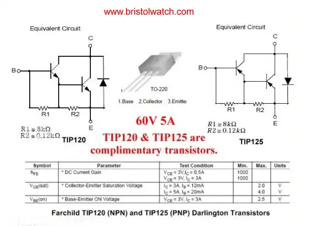
In plate 1 illustrates the packaging and internal circuitry of the TIP120 and TIP125. They are known as a complimentary pair having the same electrical specifications but opposite semiconductor polarity. They are rated at 60V, 5A, and a DC gain (hfe) of 1000.
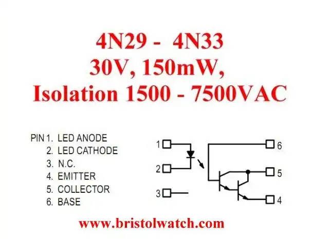
Plate 2
Because of their very high current gain Darling transistor amplifiers are used to construct sensitive opto-coupler photo transistors such as those in the 4N29.
In the case of the ULN2003A Darlington transistor array we have 7 Darlington transistor amplifiers in a single 16-pin DIP package.
See Tutorial ULN2003A Darlington Transistor Array.
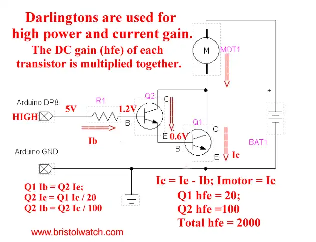
Plate 3
What is a Darlington Transistor?
A Darlington uses at least two bipolar transistors where the collectors are tied together, the emitter of smaller transistor is tied to the base of larger transistor, while circuit connections are made to the emitter from the larger transistor and the base of the smaller transistor is the input.
This is done to obtain higher power gain than a single transistor can provide. The current gain is the product of the hfe of each individual transistor, while most of the current is carried by the larger transistor.
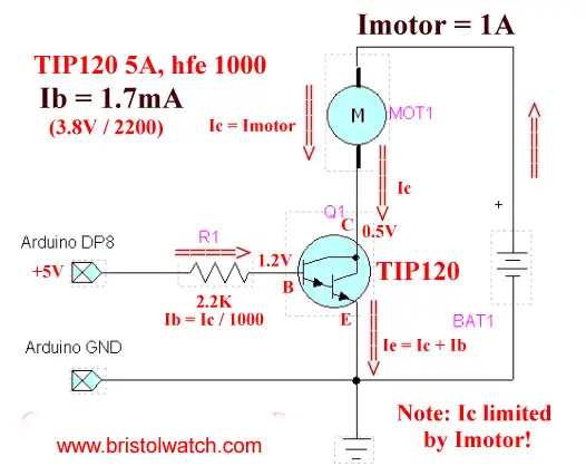
Plate 4
Illustrated in plate 4 is the typical connections to an Arduino or other micro-controller for a TIP120 NPN Darlington transistor. With a hfe of 1000 very little current is needed from the micro-controller to turn the motor on-off.
While in this case 1mA input my suffice to drive the motor at 1A extra current should be used (within limits) to assure complete cut on of the TIP120.
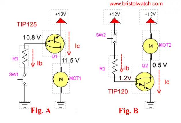
Plate 5
Plate 5 illustrates how the electrical connections differ between the TIP120 and TIP125 with a negative ground system. Note the high voltage present on the base of Q1.
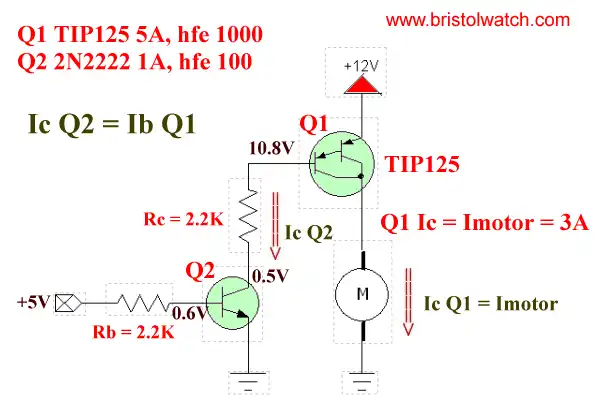
Plate 6
Plate 6 illustrates the connections for using the TIP125 PNP Darlington transistor with a 5-volt micro-controller. Because of it's opposite electrical polarity from the TIP120 an extra NPN low power driver must be used. This is because the voltage on the base is greater than 5-volts and will damage any 5-volt micro-controller.
Q2's gain of 100 can be multiplied by the gain of Q1 for a total hfe of 100,000. 2.2K is a good value to assure proper switching and limiting the Ib of the TIP120.
- Quick navigation of this website:
- Basic Electronics Learning and Projects
- Basic Solid State Component Projects
- Arduino Microcontroller Projects
- Raspberry Pi Electronics, Programming
- ULN2003A Darlington Transistor Array with Circuit Examples
- Tutorial Using TIP120 and TIP125 Power Darlington Transistors
- Driving 2N3055-MJ2955 Darlington Transistors
- Understanding Bipolar Transistor Switches
- N-Channel Power MOSFET Switching Tutorial
- P-Channel Power MOSFET Switch Tutorial
- H-Bridge Motor Control with Power MOSFETs
- Arduino Controlled IR2110 Based H-Bridge HV Motor Control
- IGBT Based High Voltage H-Bridge DC Motor Control
- More Power MOSFET H-Bridge Circuit Examples
- Build a High Power Transistor H-Bridge Motor Control
- Related:
- N-Channel Power MOSFET Switching Tutorial
- P-Channel Power MOSFET Switch Tutorial
- Test Power MOSFET Transistors, Observations
- Issues on Connecting MOSFETs in Parallel
- Basic MOSFET Transistor Test Circuits
- High Voltage MOSFET Switching Circuits
- Why Your MOSFET Transistors Get Hot YouTube
- Issues on Connecting MOSFETs in Parallel YouTube
- Simple Circuits for Testing MOSFET Transistors YouTube
See the following spec sheets:
- Basic Triacs and SCRs
- Constant Current Circuits with the LM334
- LM334 CCS Circuits with Thermistors, Photocells
- LM317 Constant Current Source Circuits
- TA8050P H-Bridge Motor Control
- All NPN Transistor H-Bridge Motor Control
- Basic Triacs and SCRs
- Comparator Theory Circuits Tutorial
Web site Copyright Lewis Loflin, All rights reserved.
If using this material on another site, please provide a link back to my site.