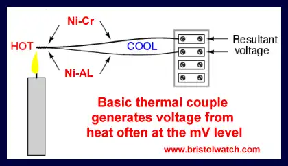
Basic thermal couple circuit uses heat on junction of
2 different metals produces a small voltage.
Simple 3-Wire MAX6675 Thermocouple ADC Arduino Interface
Warning: the temperatures used in this project can cause burns - be cautious.
More:
March 10, 2015
In this project we will interface a MAX6675 Cold-Junction-Compensated K-Thermocouple- to-Digital Converter to an Arduino micro-controller. A Type K thermal couple is inexpensive and fairly accurate. Here we have a temperature range of 0 deg. C to 1024 deg. C.
At that temperature range one can measure molten lead or zinc, flue gases in a woodstove pipe, etc. This could measure cooking oil in a deep fryer or the temperature in an oven as we bake a cake.
This is far above what we could with solid state sensors such as a TMP37 or thermistors.
The MAX6675 performs cold-junction compensation and digitizes the signal from a type-K thermocouple. The data is output in a 12-bit resolution, SPI-compatible, read-only format.
The MAX6675 is available in a small, 8-pin SO (surface mount) package.
Also see Build a Thermocouple Voltage Amplifier
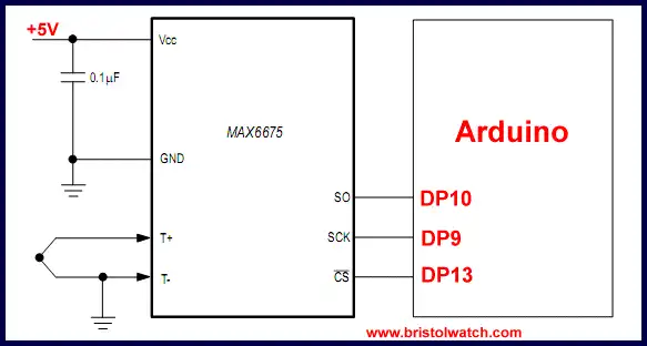
Simple 3-wire SPI interface between MAX6675 and Arduino.
Arduino Code
Above is the 3-wire connection between the MAX6675 Cold-Junction-Compensated K-Thermocouple- to-Digital Converter and Arduino. This is a read only device with a 12-bit output (16 total bits) with bit 15 (MSB) output first.
Bit 15 is a dummy sign bit and is discarded. Bits 14-3 are the actual temperature reading, bit 2 is normally 0 but if the sensor is not attached is a 1. Useful for detecting if sensor is attached. Bits 0 and 1 are discarded.
There are several "libraries" on the web for Arduino to read the MAX6675 but to me are a mess - I wrote my own more portable code anyone can use. The code works as follows in subroutine spiRead():
We declare variable "value" as an integer and set to zero. An integer variable in Arduino is 16-bits.
CS is taken LOW for 2 mSec. then HIGH to start the conversion process. We delay 200 mSec. for the process to complete.
The CS is taken LOW again to read the data. One CLK cycle from LOW to HIGH to LOW discards bit 15.
Next we use a "for" loop to retrieve the next 15 bits (14-0) that are stored in variable "value".
Next we test bit 2 to see if the sensor is connected. A 1 means no sensor and a value of -1 is returned to the main program.
If bit 2 is 0 everything is OK, "value" is shifted right three places and the Centigrade integer value is returned to the main program.
Back in "loop" if a -1 is returned to variable v a message "No sensor" is generated. Otherwise v is multiplied by 0.25 to get the temperature in Celsius which is converted to Fahrenheit then displayed on the serial monitor or on a LCD display.
Arduino code: therc.txt
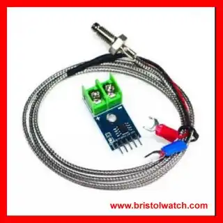
MAX6675 Thermal Couple amp
with Type K sensor.
- Arduino and Raspberry Pi
- Arduino PWM to Analog Conversion
- Arduino Analog Digital Conversion Voltmeter
- Better Arduino Rotary Encoder Sensor
- Simple 3-Wire MAX6675 Thermocouple ADC Arduino Interface
- Raspberry Pi and MAX6675 thermal-couple sensor
- Quick navigation of this website:
- Basic Electronics Learning and Projects
- Basic Solid State Component Projects
- Arduino Microcontroller Projects
- Raspberry Pi Electronics, Programming
- Digital Circuits:
- Simple Schmitt Trigger SN74HC14 Square Wave Generator
- Introduction to RC Differentiator Circuits and Uses
- SN74HC14 Square Wave Generator uses SN7476 JK Flip-Flop
- SN74C14 Three Output Pulse Generator Circuit
- Astable CD4047 Geiger Counter Power Supply
- CD4047 Monostable Multivibrator Circuit
- Basic TTL Tri-State Buffer Circuit Examples
- Tutorial NOR Gate SR Latch Circuits
- Tutorial NAND Gate SR Latch Circuit
- Tutorial OR-NOR Circuits Including Monostable Multivibrator
- Brief Tutorial of XOR and XNOR Logic Gates
- LM555-NE555 One-Shot Multivibrator AC Power Control
- YouTube:
- Three Output Digital Pulse Generator
- Digital Circuits:
- Two Transistor LED Flasher Circuit
- Astable CD4047 Geiger Counter Power Supply
- CD4047 Monostable Multivibrator Circuit
- Basic TTL Tri-State Buffer Circuit Examples
- Tutorial NOR Gate SR Latch Circuits
- Tutorial NAND Gate SR Latch Circuit
- Coils for Highly Selective Crystal Radio
- Neon (NE-2) Circuits You Can Build
- Understanding Xenon Flashtubes and Circuits
Web site Copyright Lewis Loflin, All rights reserved.
If using this material on another site, please provide a link back to my site.